16×8 LED Matrix Display
The 16×8 LED Matrix clock was a project I built for my office. I wanted to have a clock for my desk which was a little unusual. I decided to build a 16×8 red LED matrix display and then interface this with a PIC18F2550 based circuit including a real-time clock and a temperature sensor.
The final result of this project can be seen in the following video:
Construction
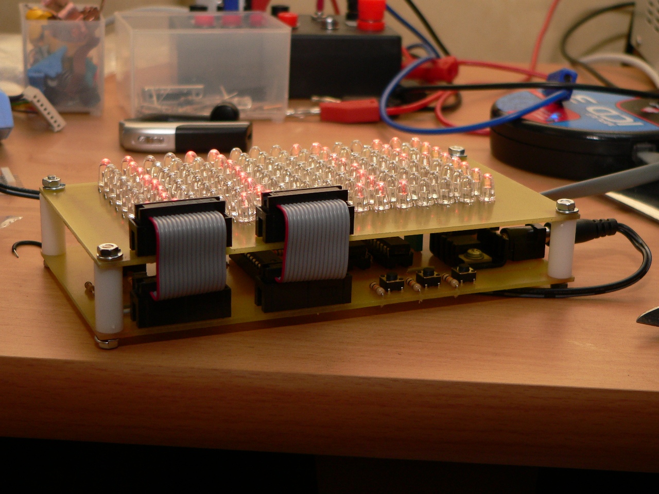
The clock is made using 2 PCBs, the top PCB contains all the LEDs and is connected to the bottom PCB which contains the display driving electronics as shown in the following picture.
As you can see from the following circuit diagram the display controller consists of a PIC18F2550 which is connected via SPI to an A6276 16-bit serial LED driver (which controls the columns of the display) and a 74ACT164N serial 8 bit shift register (which control the rows of the display). This means that it only requires 8 cycles to update the whole display allowing a bright and stable image. Since the LED matrix draws more current than the shift register can supply the chip is connected to the display via BC337 transistors which switch the current.
The real-time clock is a DS1302 which is connected to the PIC using a modified SPI style interface, the DS1302 uses a standard SPI style 3-wire interface however the data wire can be both input and output, therefore it is not connected to the on-board SPI interface of the PIC (unlike the other SPI chips). The clock chip requires its own 32.768 Khz crystal and can have a battery backup included if required, however I did not include one in the design.
The temperature sensor is a LM35 precision centigrade sensor and is connected to the PIC using a standard analogue port.
To set the clock and control the device there are three push-buttons mounted on the lower PCB which act as up, down and enter buttons. The code includes debounce and auto-repeat code for the buttons to make setting the clock as easy as possible.
There is a small speaker mounted on the control PCB to allow alarms and other audio functions to be added in the future (however the current code does not utilise this at the moment). This isn’t currently shown in the circuit diagram since I added it in during the PCB design as an after-thought.
I also included an RJ11 6/6 connector to allow easy reprogramming using the Microchip ICD3 programmer/debugger.
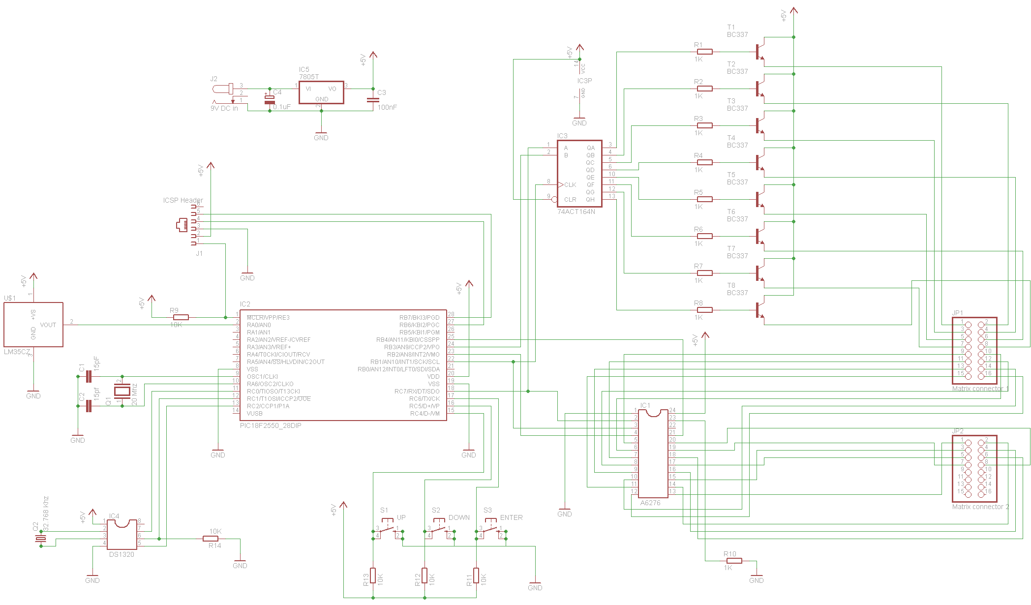
Please note that there is no circuit diagram for the display PCB (it was not necessary to draw one since it is so simple). The negative side of the LEDs connect to the A6276 (since it is a ‘sink-driver’) and the positive to the 74ACT164N.
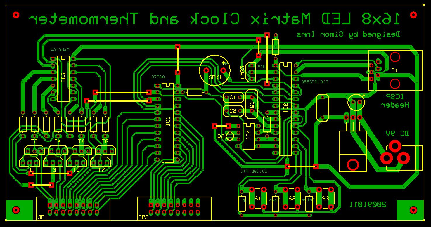
PCB Layout
The PCB layout was designed using PCBexpress. A picture of the control board showing the component placement and a PDF file containing scale drawings of both boards are available below:
Files for download
The code was written in MPLAB using the HiTech C compiler for the 18F. A zip file of the MPLAB project is available below. Please note that this code is released under a GPL licence.
Control board PCB layout PDF diagrams:
MPLAB Project Zip file of GPL’d code:
This project was excellent, little is seen so much quality on the network.