LED Colour Organ
Contents
I’ve always been interested in sound-to-light conversion since both playing music and electronics are both hobbies of mine, so I decided it would be great to build a ‘colour organ’ of some sort. Much surfing and googling later revealed that there didn’t seem to be any pre-existing designs available on the web that suited my purposes. Here was my initial wish-list:
- 3 Channels
- Microphone driven (does not need a wired connection to sound source)
- Microprocessor controlled (preferably PIC MCUs)
- Both tone and volume sensitivity
- LED light driving (not incandescent bulbs)
- No ‘sensitivity adjustment’ knobs or controls
Nearly all the existing designs I found used direct switching of the lights (with no software control in between) and contained manual potentiometers for light sensitivity and overall gain setting. Furthermore, I couldn’t find many references to the frequency filter circuitry explaining the frequencies the circuit was designed to detect and why (it seems most published designs are based on other published designs leading to fairly ‘sloppy’ audio-stage circuitry).
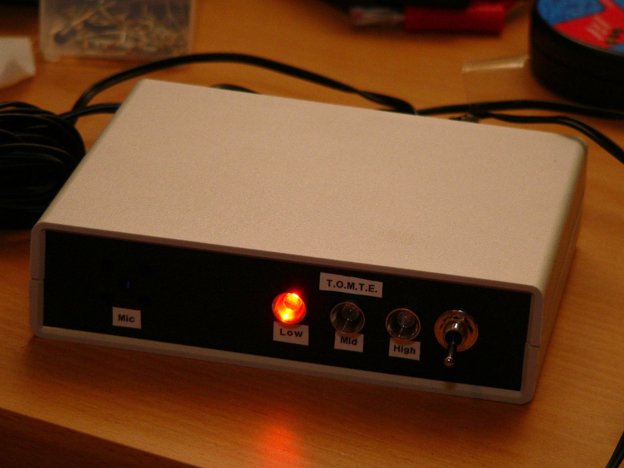
So it was time to brush up on op-amp filter design and build something myself. At the local hardware store I found some strings of LED lights (for Christmas decorations) and thought that wiring up a Christmas tree as a colour organ would be a pretty fun thing to do. From that T.O.M.T.E. was born (Tone Operated Microprocessor Tree Enhancement), details of which you can find below along with detailed construction notes. (for the non-Swedish reader, Jultomte is Swedish for Santa Claus, hence the funky abbreviation!)
The sound processing circuitry for TOMTE is probably a little over-the-top for the application it is used for here, however it represents a good quality sound-to-light interface design which is probably useful for a number of other light/audio projects I can think of, so even if you don’t intend to build the Xmas decoration I designed, the circuitry is still useful.
The following block diagram shows the overall design of TOMTE:
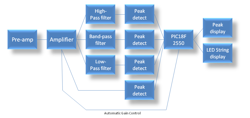
The microphone is connected to a pre-amplifier (because microphones produce so little electricity) and then on to an amplifier (which has automatic gain control from the microcontroller), the signal is then split into 3 frequency ranges (low, mid, high). Finally the sound is passed through peak-detectors (actually these add a little gain and convert the AC audio signal into DC) which is then measured using the ADC of a PIC18F. The PIC MCU then controls the available lights and the gain of the amplification block (which is why there is also an unfiltered audio feed to the PIC for ‘listening’ to the overall gain).
Video Demonstration
For a complete demonstration of the unit and its capabilities please take a look at the following video:
Functional Block Design
Microphone pre-amplifier
The microphone pre-amplifier is a simple electret microphone amplifier which uses a single op-amp from the LM324 quad op-amp IC. This circuit provides a moderate amount of fixed gain to the microphone signal to allow the later stages to function even with a relatively quiet music source. Since electrical noise and power-line jitter is critical in this stage large decoupling capacitors are used to remove as much noise as possible so that interference isn’t introduced at the primary audio stage.
The advantage of a separate pre-amp is that you can easily modify the circuit to run from a standard audio line-in by bypassing the pre-amp and wiring the line-in directly to the amplifier. If you use a ‘switched’ socket you can even make the line-in jack disconnect the microphone when plugged in and therefore make the unit run from either source.
Amplifier
The amplifier consists of two ICs; firstly the output from the pre-amplifier is passed through a Microchip MCP41010 10K digital potentiometer (with SPI serial interface) which allows the microcontroller to change the input gain from the pre-amplifier to the amplifier. The amplification is performed by a LM386 low-power audio amplifier which I chose because of its simple design and the fact it runs happily from a single 5V supply. The LM386 can provide up to 200x gain (by placing a capacitor/resistor combination between pins 1 and 8) but in the TOMTE circuit it provides 20x gain which was enough to get a ‘loud’ signal without any clipping even at moderately low sound-levels to the microphone.
Filters
The filter design was one of the most crucial elements of the circuit since the design and range of the frequency filter directly affects the light activation pattern according to the input sounds. The trick is the selection of the right frequency ranges to get the best ‘feeling’ of the lights following the sound. This is not an exact science since the ranges of frequencies and the quality of the ‘following’ is going to vary based on the style and genre of music as well as your own personal tastes. I found the best way to choose the filter ranges is to mock-up the filters on a breadboard and play with the frequencies until you get the optimum results for your purposes.
My overall aim for the filter design is shown in the following conceptual chart:
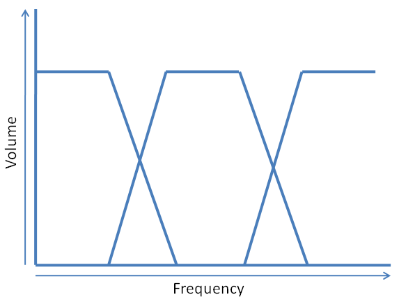
As the diagram shows, the aim is to get a good coverage of the frequency range without the filters overlapping too much (which will cause the lights to fire together too often ruining the effect). For the TOMTE design I used a low-pass filter with a response of <300Hz, a band-pass filter with a 1-1.2Khz response and a high-pass filter with a response of >3Khz. It should be noted that the frequency response of the microphone provides the highest and lowest stop-bands overall.
Low pass filter
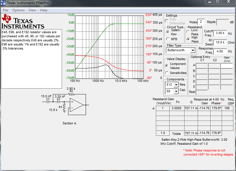
The low pass filter was designed using FilterPro from Texas Instruments which takes a lot of the hard maths work out of the design. You can see the screen output of the tool for the low pass filter in the following screenshot:
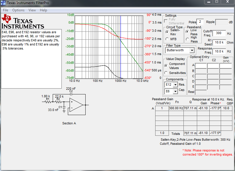
As with all the filters the resistor and capacitor values have to be altered to standard values. Since I keep a stock of 5% E6 and E12 ranges these are what I used in the final design. Of course, more accurate components with smaller tolerances would make the filters more accurate, but for this application this isn’t too important.
High pass filter
The high pass filter was designed using the same tool as the low pass filter above. Here is a screenshot of the output:
Band-pass filter
For the mid-range filter it is necessary to use a band-pass filter. I decided on a narrow band-pass filter (a filter which has a single ‘peak’ frequency) since my attempts to use a wide band-pass filter caused the mid-light to be on too much (a wide band-pass uses a combination of a high and low filter to pass through a range of frequencies). Since the TI tool (used for the low and high filters) does not support band-pass design I used Microchip’s Filterlab (another free filter design program) to produce the band-pass. The following diagram shows the ideal frequency response of the filter:
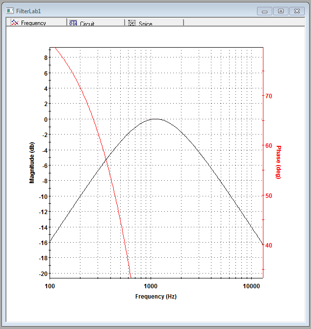
The crucial part of the diagram above is the peak above -3dBs which shows that the filter should be peaking in the range of 500Hz – 2.5KHz with 0dBs peak in the range of 1KHz – 1.2Khz.
Peak detector
The initial sound input from the amplification stage is an AC signal which is biased around a ‘virtual ground’ of about 2.5Vs (half way between 0 and 5Vs since this design has a single +5V supply). Since the Analogue-to-Digital converters on the PIC MCU operate between 0 and 5Vs it is preferable to have a swing of 0V for silence and 5Vs for maximum volume. The peak detector circuitry re-biases the signal to 0V and the output diode prevents any signal below 0Vs. The opamp also provides a little gain meaning that the output to the PICs ADC is in the (theoretical) range of about 0-4Vs however this is considerably lower in practice since the input signal from the mic is not always at maximum.
A small capacitor on the output of the peak detector holds the high-frequency signals a little (basically it makes the peaks drop at a slower rate) which compensates for the relatively slow sampling rate of the PIC’s ADC. Without these capacitors the PIC will ‘miss’ peaks which happened in between samples.
The forth peak detector performs the same task as the others, but on the raw unfiltered output from the amplification stage. This is to allow the PIC to measure the overall input gain as well as the individual frequency peaks.
If you’re not interested in the sound levels but only the peaks you could replace the peak detectors with a comparator which would provide a clean TTL level signal to the PIC (or you could drive LEDs from the comparators without even using a microcontroller).
Microcontroller
The microcontroller is a PIC18F2550 which is a good combination of available ports, size and speed. The PIC is connected to the digital potentiometer using an SPI serial interface. The peak LEDs are directly driven from the PICs pins since the power drain is around 60mAs for all three lights (the PIC’s rated maximum is 200mAs for all pins). I have also included a 3-position switch to allow the user to switch ‘modes’ or provide some other input to the microcontroller.
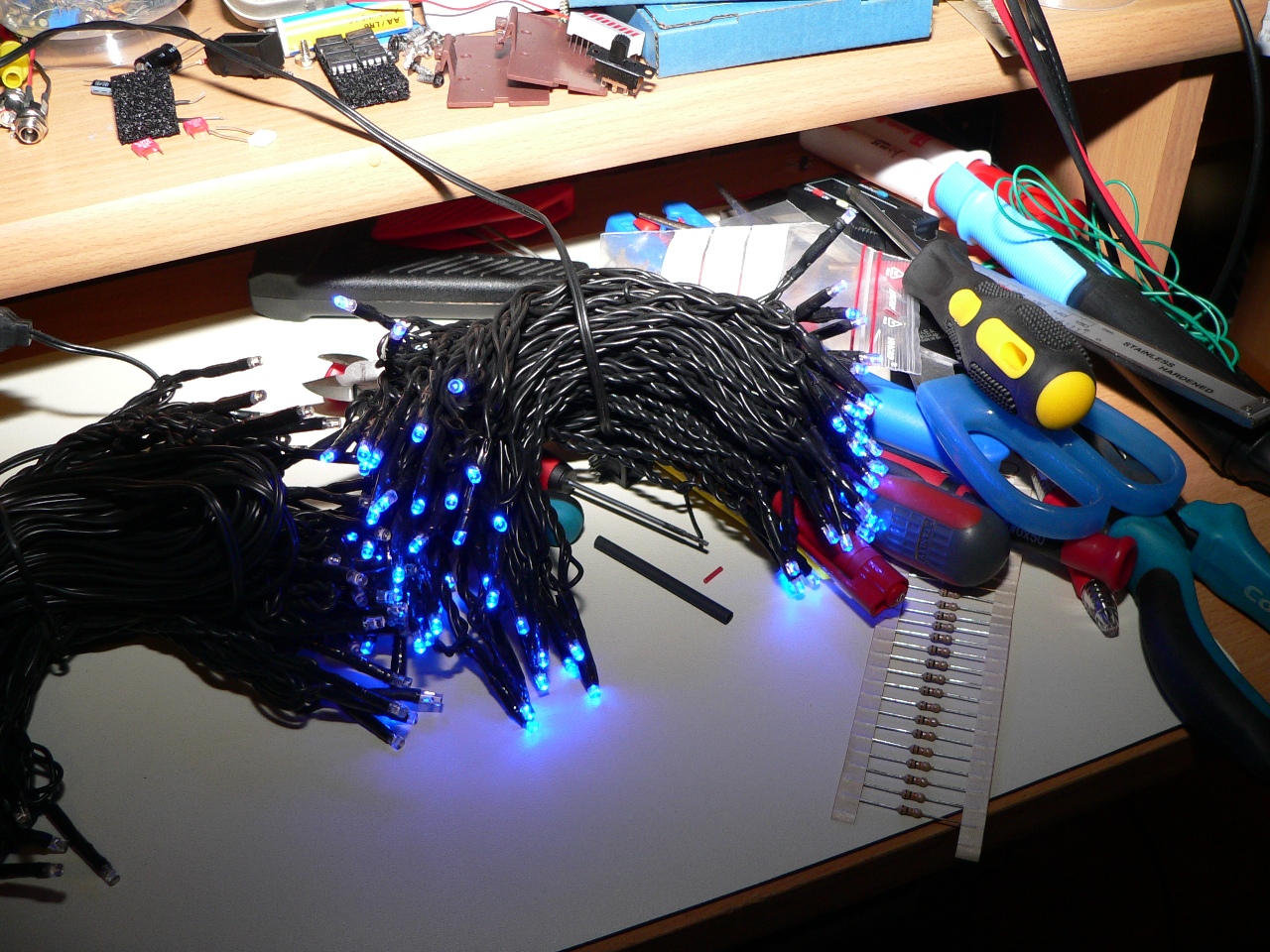
LED light strings
The LED light strings are 3 strings containing 80 high intensity LEDs in each string. Each string is designed to be powered by a 24V 200mA supply. This means the total current drain is 600mAs, three times the PICs rated maximum. To drive the LED strings a ULA2004 chip is used to sink the current from the LEDs. It is switched by the PIC using a standard 5V signal, this controls the 24V current sink to operate the lights.
Power supply
Since I wanted TOMTE to run from a single power supply it was necessary to power the whole unit in accordance to the power requirements of the LED strings. For this I purchased a 24V 1000mA unregulated supply (in reality it seems to supply around 29Vs). This meant I had to include 2 separate power regulators, one for 24V and one for 5V.
Since 24V to 5Vs is quite a wide leap, I decided to use a switching regulator which can provide the regulation without generating very much heat. This means I don’t need to include a bulky heatsink in the final design. For this I used a LM2576 simple switcher.
For the 24V supply I used an LM350 variable regulator. Since this is not regulating away too much power it also doesn’t need a heatsink (actually I tested this theory by running the PSUs overnight with all LED strings running, both chips were around 27C after 8 hours of operation). The LM350 actually provides a little above 23Vs (due to the values of the adjusting resistors), it should be possible to up this value a little to get slightly brighter LEDs if required.
Both of the power supplies are capable of handling up to 3 Amps of current, so this design can easily be scaled up for more light strings by swapping the PSU for a more powerful version (note that the ULA2004 contains 7 drivers also, only 3 are used in TOMTE).
Since the LM350 is variable you can easily adjust the control resistors to supply more or less voltage (if your LED strings are not 24V like the ones I purchased), although the ‘per string’ current consumption should not exceed the ratings for the ULN2004 chip or the PSU’s maximum mA output.
Circuit Schematics
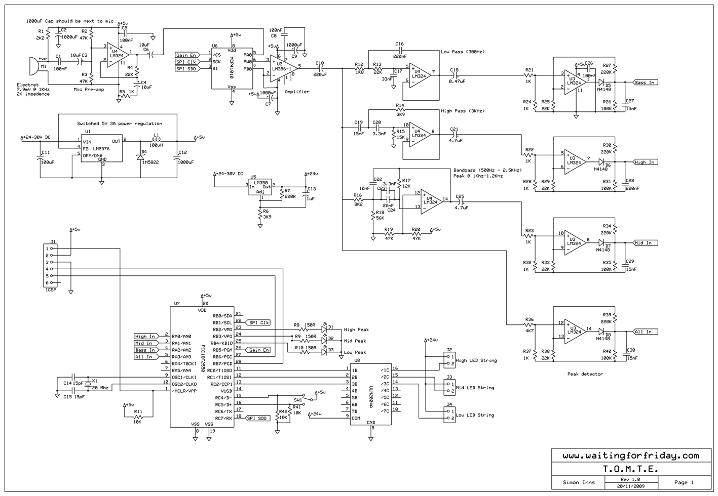
The following schematic diagram shows the design for TOMTE, it was produced using expressSCH (a good free program). If you follow the block diagram above it should be pretty straight-forward to understand the schematic:
PCB Layout and design
I wanted to fit the whole circuit into a Velleman G738 enclosure which measures 140x110x35mm, it was a bit of a squeeze since I wanted to make the PCB myself (and I only have a single-sided UV lightbox).
The following picture shows the PCB layout including the silk-screen layer which indicates the position of the components on the board (the full layout files and original schematic are included in a zip file at the bottom of this page):
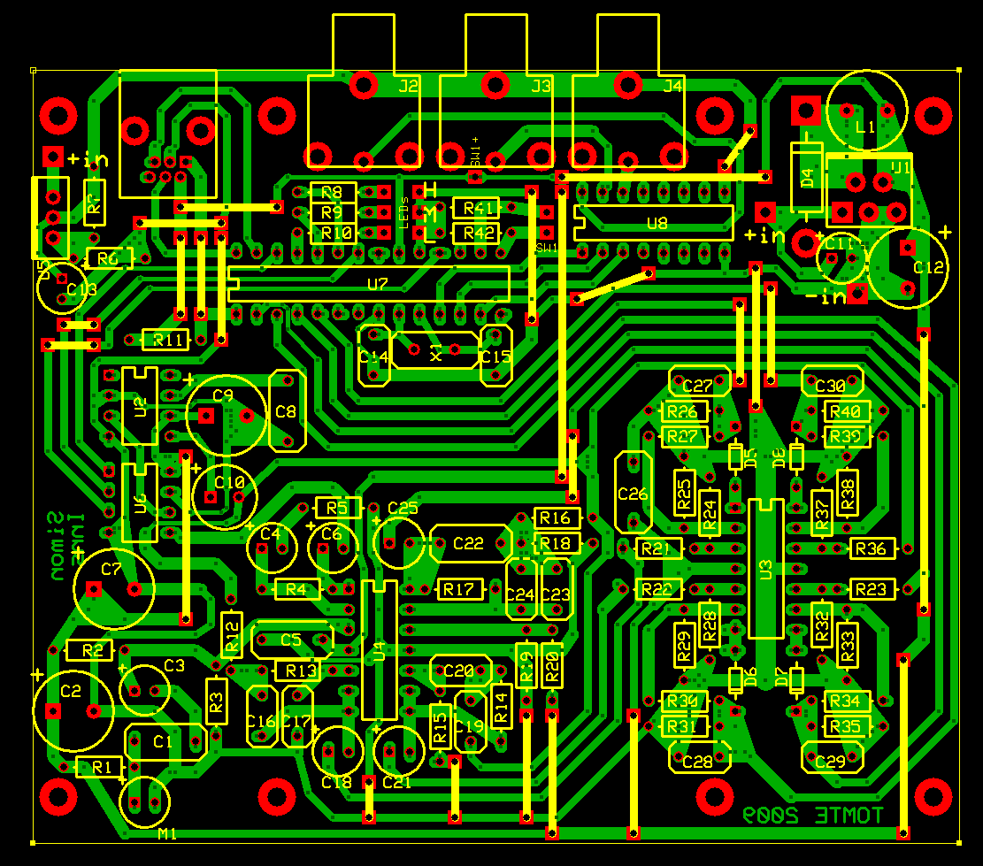
I decided to use some PCB mounted RCA sockets for connection to the LED strings (mainly because I had plenty of them available) but any low power 2 pin connector would suffice. The LEDs and switch are separate from the PCB so they can be mounted on the front panel of the box.
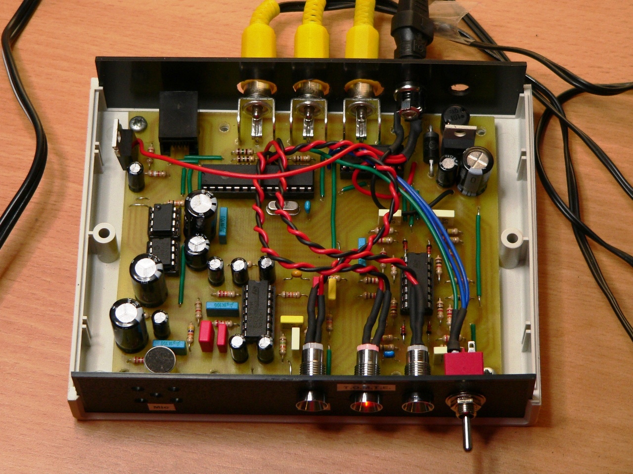
The following image shows the completed circuit board mounted in the box with all the external panel components also in place:
PIC MCU Software
Operating instructions
The current version of the TOMTE software provides 3 operation modes which depend on the position of the toggle switch:
- Up – Colour organ only mode – The 3 lights are PWM controlled according to the sound detected by the in-built microphone
- Down – Light display only mode – The 3 lights are flashed and dimmed in 5 sequentially displayed patterns
- Middle – Sound activation mode – TOMTE runs in light display only mode until sound is detected, then it switches automatically to colour organ mode and vice-versa
When TOMTE is in the ‘up’ mode the peak LEDs display the same thing as the LED strings. In the ‘middle’ and ‘down’ mode the low peak LED is illuminated whilst the software waits for sound. In the ‘middle’ and ‘Down’ mode the high peak LED will flash if a clapping sound is detected.
When TOMTE is displaying patterns (either in ‘down’ or ‘middle’ mode) it is listening for a for a clapping sound. If you clap your hands together it will shift to the next light pattern (note there are 5 different light patterns).
Looping state-model
The software (in all modes) is based on a core loop which continues to run independent of the mode. All of the functions are provided by the loop using a state-machine model; all timing is provided by a tick-counter which is driven from the PIC’s timer0. This basically means that the software remembers it’s state from loop to loop and only alters state periodically based on the tick counter, so adding in more patterns is relatively straight forward. This style is necessary since the ‘middle’ mode requires the software to continue to process the average gain input whilst displaying the light sequences.
Automatic sound detection
The sound detection is a type of ‘de-bounced’ switch which is based on the average input levels over time, there is a built in on/off tolerance which can be altered to make the unit more or less sensitive to both the sound coming ‘on’ and going ‘off’. The software is much more sensitive to the sound coming on than off to prevent TOMTE flicking between modes in an undesirable fashion.
PWM LED Brightness control
The current version of the software supports 32 levels of brightness via PWM to the 3 lights.
Automatic Gain Control
The software samples the ‘all-in’ sound channel 200 times and calculates the average sound level. The volume level is gradually adjusted until the average sound level is at the target level. This provides a fairly stable gain output from the 3 channels meaning that the ‘peak’ value for each of the channels remains fairly constant independent of the actual sound levels received by the microphone. The AGC means that the peak levels for the channels can be hard-coded into the software and no channel sensitivity setting is required when the sound organ is running. Since the ADCs receive a fairly constant gain level the reaction of the colour organ does not change significantly once the input is above the minimum volume level required by the hardware to operate.
It’s possible to alter the minimum level at which the colour organ operates by manipulating the designed AGC gain level and the peak levels in the software. I’ve set it to (what I think) is a good level, but you can easily make it more or less sensitive and make the lights flash more or less.
The software also allows you to alter the speed at which the gain level is adjusted. High speeds means that the AGC operates faster but at the cost of a stable sound level (once the audio is around the target level the AGC will oscillate around the target level, faster adjustment of gain means this oscillation will be more pronounced).
Project files for download
Please note that I haven’t tested the project extensively yet (this will probably happen over Christmas), so I make no promises that the code is bug free (although it seems to work fine from the testing I have done in my ‘lab’).
There are two files available for download:
MPLAB Project zip file containing TOMTE’s code:
Circuit Schematics and PCB design files in expressSCH and expressPCB format:
I will note any issues I find in the ‘possible improvements’ section below, so please check that before working with any of the files.
If you make any good alterations to the software or hardware I would love to hear from you and get a copy of your changes. My contact email address is simon dot inns at gmail dot com.
Possible Improvements
This section contains some additional notes about things that could be improved/reworked.
Hardware
- High-frequency channel gain is low compared to the other channels – perhaps adding more gain in the filter or peak detector would improve this?
- RJ11 6/6 ICSP jack is wired incorrectly (pins are reversed) – I will probably revise the PCB design to fix this shortly although it’s not a big issue since the ISCP jack is not really required after software development
- Peak detectors are borrowed from elsewhere – It would probably be better to design these from scratch (like the filters) to get a more optimal output
- PCB density – could probably be improved
- Line-in jack – could easily be included
- RCA plugs – in the current design the outside of the RCA plug is +ve, this should really be the inside of the jack since it will present a potential short between the RCA plug and the outside of the power jack if the unit was mounted in a metal box.
- When the peak LEDs are switched on there seems to be considerable interference to the high-channel (or more exactly to the pre-amplifier), this interfered with the automatic sound detection. As a fix the LEDs are not flashed whist TOMTE is waiting for sound. This is probably due to the AGC which means that the input gain is always maximum when there is no sound present since it does not seem to effect the colour organ whilst it is running.
Software
- The AGC function could be altered so that the gain-step is reduced as the gain approaches the desired level, this would allow the AGC to track to the desired level quickly without unwanted gain oscillation around the target
- Only 5 patterns are coded – more would be nice
Making the PCB
Here are some extra pictures of the PCB development process just for the curious:
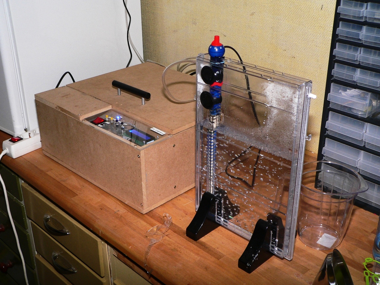
My home made UV light box and my etching tank
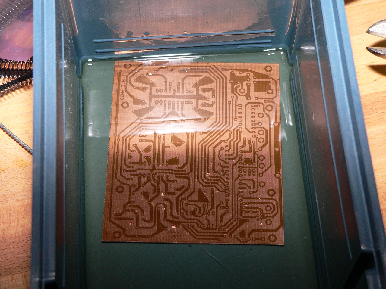
PCB being developed after UV exposure
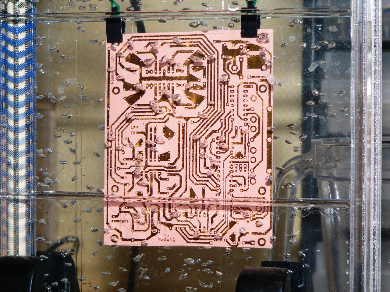
Etching the PCB in the etching tank
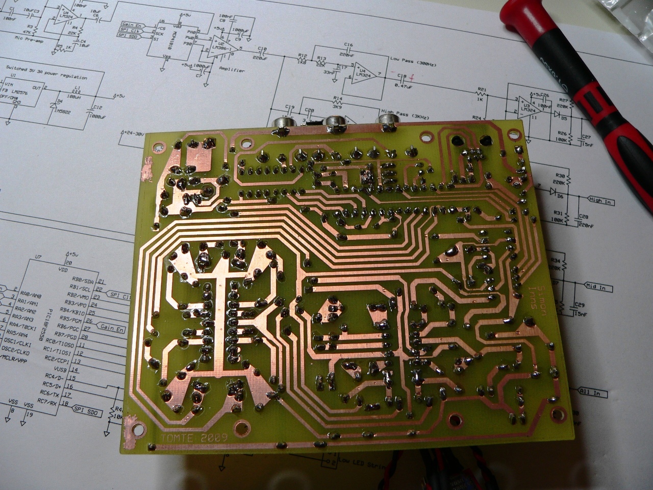
The solder-side of the completed PCB