Acorn BBC Master and Electron Cartridge Breakout
Contents
This project provides a simple breadboard adapter/breakout board for prototyping cartridges for the Acorn BBC Master and Acorn Electron 8-bit computers.
The design consists of two PCBs, the first plugs into the computer’s cartridge slot and the second is designed to plug along the edge of a standard 2.54mm pitch breadboard. The two boards are connected by a length of 50-way ribbon cable.
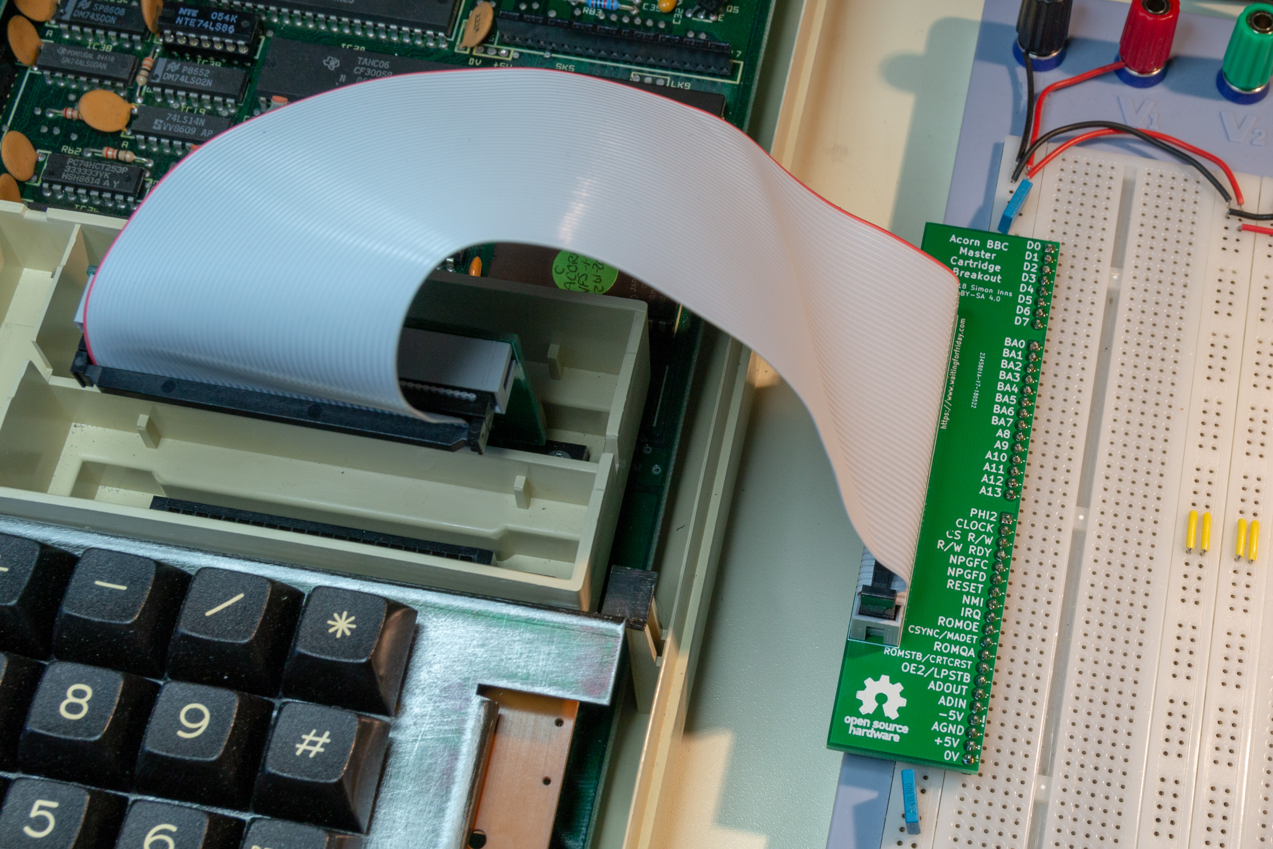
Cartridge and header boards
Hardware
Cartridge adapter board schematic
The cartridge header board groups the various signals from the Acorn cartridge edge-connector into 3 logic groups, namely data bus, address bus and signals. This makes the organisation of the signals on the breadboard much easier to work with. The board also provides a 500mA polyfuse on the 5V supply and a 200mA polyfuse on the -5V supply. Both polyfuse ratings can be adjusted to individual requirements (and the 500/200mA ratings are just a suggestion). The polyfuses can also be completely omitted and bridged using wire (if not required).
Connection to the breadboard adapter is supplied by a standard 50-way IDC connector (similar to that used by SCSI-1 cables). The schematic is as follows:

Cartridge adapter schematic
Breadboard adapter schematic
As the signals are logically grouped by the cartridge adapter, the breadboard adapter is a simple 50-way IDC to SIL header adapter that can be plugged directly into a breadboard. As the interconnection is via a 50-way IDC connector, other end-adapters can also be developed to plug into the cartridge adapter if required. The schematic is as follows:
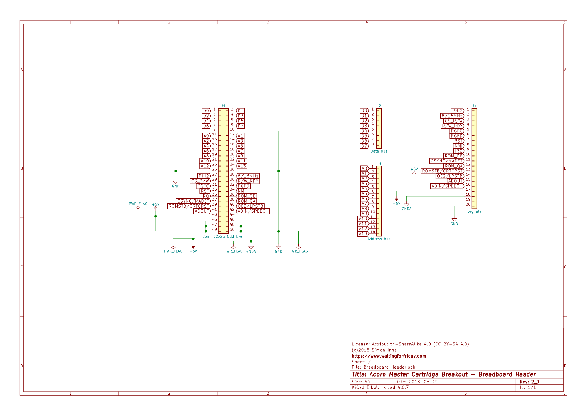
Breadboard header schematic
Cartridge adapter PCB design
The cartridge adapter PCB provides an edge connector that is inserted into the cartridge slot of the Acorn computer. The PCB is shown in the following picture:
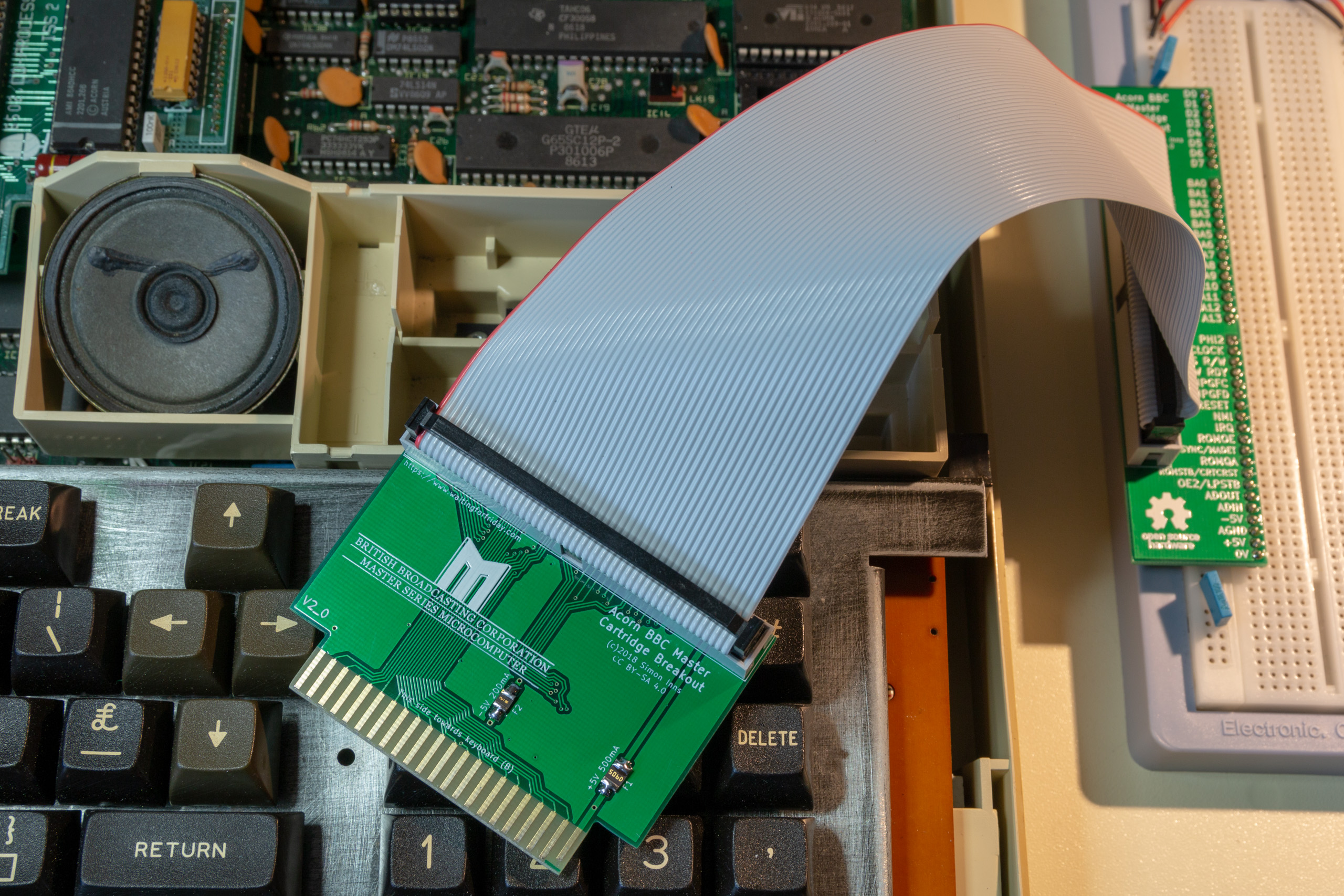
Cartridge Adapter PCB
As the cartridge adapter uses an edge connector it is recommended that the PCB be finished with ENIG (gold plating) to ensure a good (and long-lasting) connection. The following specifications are recommended for manufacture:
- Layers: 2
- Dimension: 66mm x 51mm
- PCB Thickness: 1.6mm
- PCB Colour: Green
- Surface Finish: ENIG with ‘gold fingers’
- Copper Weight: 1oz
- Material Details: FR4-Standard Tg 140C
Breadboard adapter PCB design
The breadboard adapter provides a 50-way IDC connector routed to the 44 signal pins used by the cartridge interface. The signal pins are arranged as a single-row with 2.54mm pitch so the board can be directly inserted into a breadboard as shown in the following picture:
Breadboard adapter
The following specifications are recommended for manufacture:
- Layers: 2
- Dimension: 66mm x 51mm
- PCB Thickness: 1.6mm
- PCB Colour: Green
- Surface Finish: HASL (with lead)
- Copper Weight: 1oz
- Material Details: FR4-Standard Tg 140C
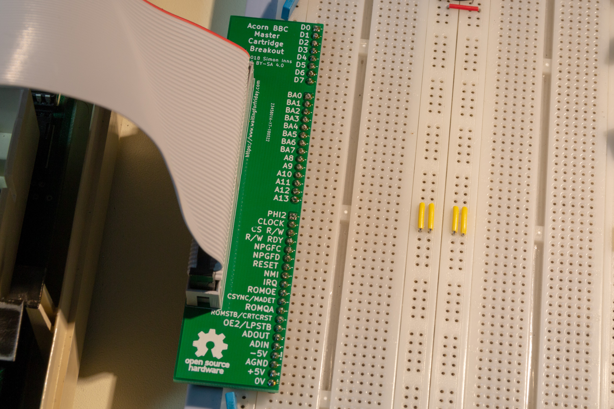
The breadboard adapter is clearly labelled and shows the signal names in accordance to the cartridge interface pin-out provided by the New Advanced User Guide:
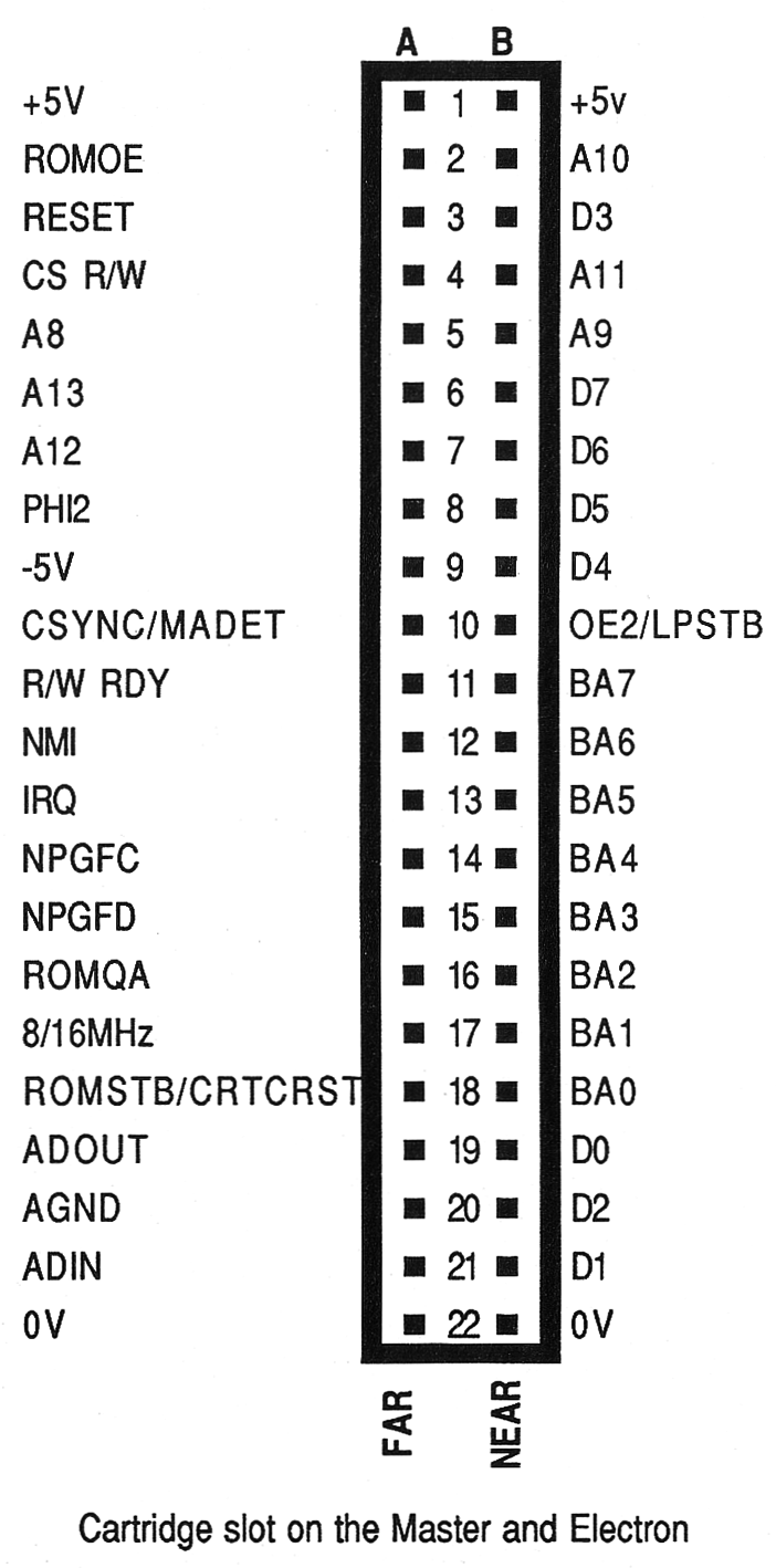
Master cartridge pin-out
Files for download
All project files are available from the project’s GitHub repository. Ready-made gerber files for the PCB can be found in the releases section.