Simon18F
Simon18F is a project to replace the custom MB4850 processor of the MB Electronics Simon game with a PIC18F2550; initially to emulate the original Simon games and, later, to enhance the existing games and add new ones.
For a video of this project including commentary please see the following:
Hardware
The Simon18F processor board is based on the PIC18F2550 processor. I chose this PIC since it is a good combination of small-size and speed (48 Mhz). Since there is virtually no difference (in price) between the PIC16Fs and PIC18Fs the extra speed, memory and capabilities of the processor will enhance the abilities of this board greatly.
As an alternative the PIC18F1320 could be used, however I’ve found the chip to be far to sensitive when run at 40 Mhz (it requires capacitors everywhere!).
Circuit Schematic
The following diagram shows the circuit schematic for the Simon18F board:
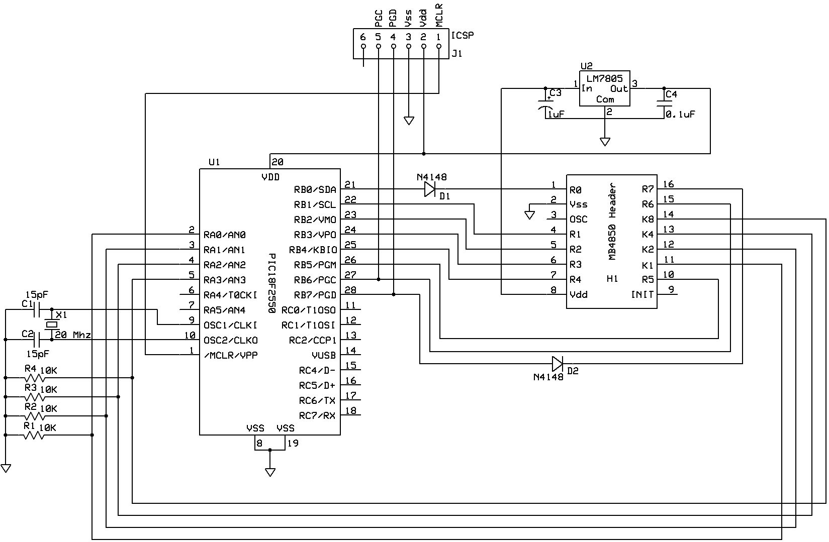
The board is a very basic PIC18F set up with a 5V regulator so the PIC can be powered by the existing 9V battery in the MB Simon game. An external 20Mhz crystal is also included which allows the PIC to run at the full 48Mhz. The extra speed is useful for PWM control of the LEDs and generating the sound for the game. The input and output ports of the MB4850 processor are wired to the equivalent ports on the PIC.
Strip-board design
I decided to make the processor board on a small piece of strip-board which can fit under the mainboard inside the game’s case. This makes it easy to make and also allows the board to be expanded if required (you could use the extra ports for an LCD screen, or as a serial/USB port to connect the game to a computer (I’ve deliberately left the required pins unused)).
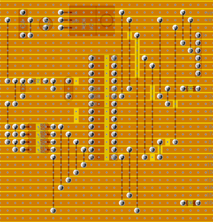
The following pictures show the top and bottom sides of the stripboard and the component placement:
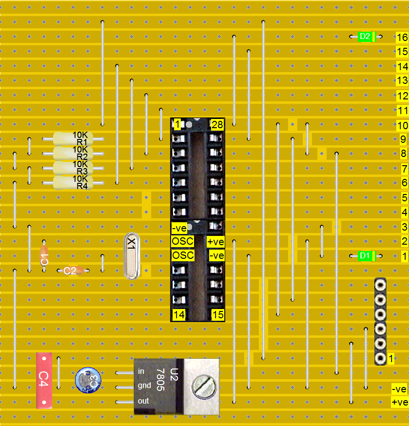
You may need to adjust the design a little if your component sizes vary from those shown.
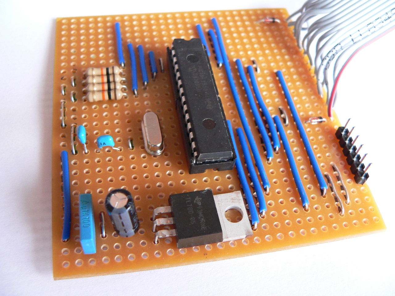
The header connector is connected to the processor board via a 16 way ribbon cable. The other end of the cable is soldered to a small piece of stripboard that has two single-row header pin strips soldered on which fit into the processor’s socket.
Here is a picture of the completed processor board:
Please see the video link above for details of how to fit the board into the game.
Software
Design
The software is based on the information from my previous project Reverse engineering an MB Electronic Simon game and attempts to follow the flow and timing of the original Simon as closely as possible. I also used my original Pocket Simon as a comparison to make sure the feel was right.
The software was designed using an SDL flowchart to ensure that the logic was correct (and efficiently written) before programming. The logic of the 3 games available on the Simon is shown in the flowchart to the right of the page.
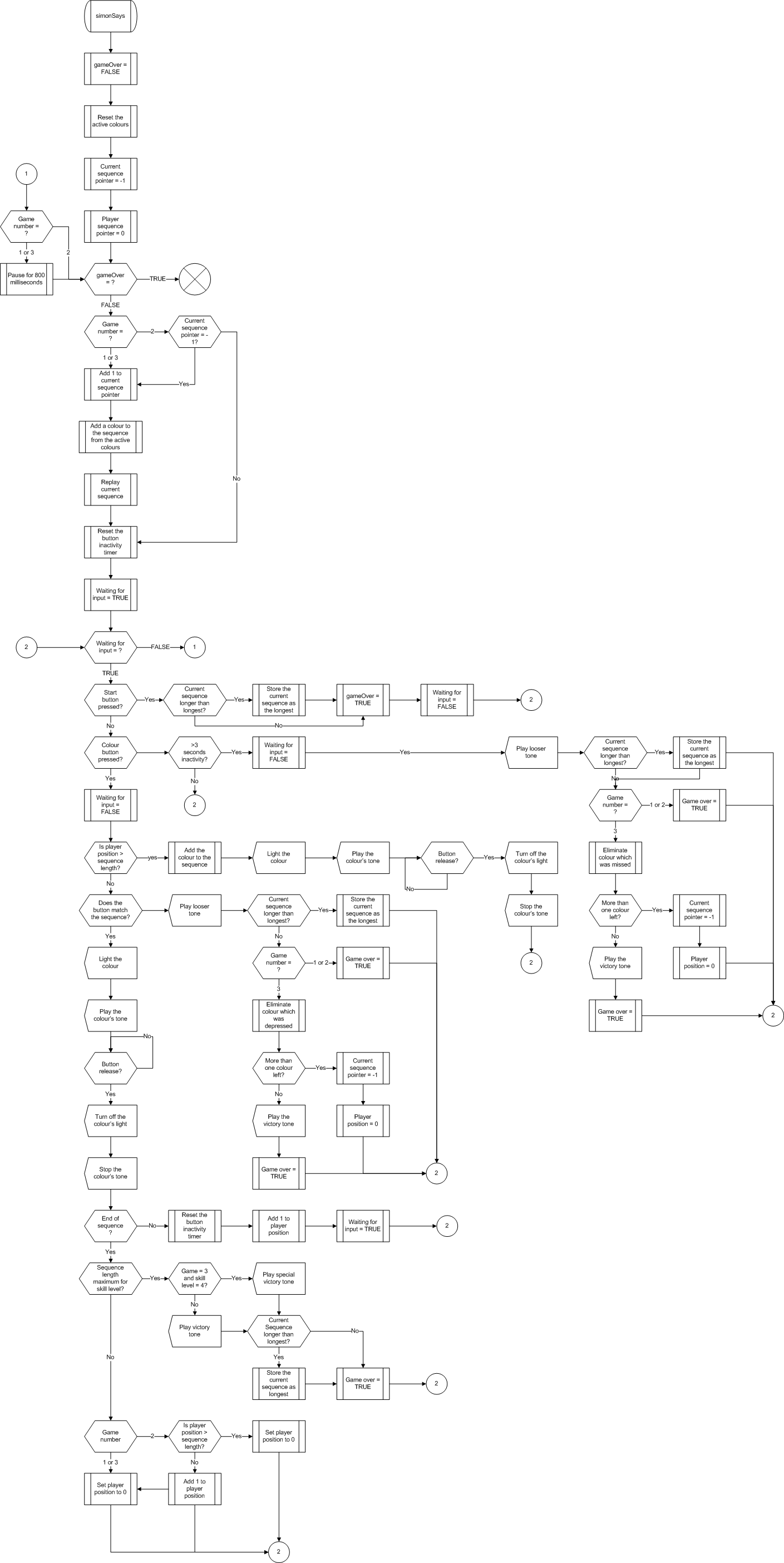
The code follows the flowchart using matching comments wherever possible; this makes it easy to trace and understand the C code.
To make it as easy as possible to alter and adapt the Simon18F code I decided to use a high-priority interrupt to generate the sound and a low-priority interrupt to control the LED PWM dimming routines and the button scanning and debouncing. All communication between the hardware affecting interrupts and the game logic are perform through a C structure found in hardware.c.
Modules
Here is a list of the modules found in the software with a quick explanation of what the module is for:
- delay.c – Contains the delay timing routines
- game.c – Contains the logic for the 3 Simon games
- hardware.c – Contains the hardware definitions and the structures required for
- communication between the game logic and the hardware handling interrupt routines
- interrupt.c – Contains the high-priority sound generating interrupt and the low-priority LED
- and button control
- lights.c – Contains utility routines to make controlling the lights easier
- main.c – Main procedure, initialise the PIC and sets up the hardware and software
- sound.c – Contains utility routines to make controlling the sound easier
The software was compiled using Hi-Tech C Pro for the PIC18 MCU Family (Lite) V9.63PL2 which is freely available over the web.
Files for Download
Please click the following link to get a copy of the GPLed source code for this project as a zip file (this is an MPLAB project exported as a zip file so you should be able to reload it into your MPLAB IDE):