C64 VICE Front-End
Contents
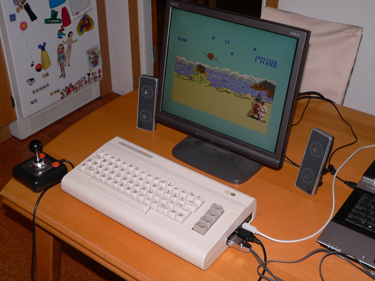
The aim of this project was to create a front-end for Commodore 64 emulation using VICE. One of the primary problems with emulators (especially for machines from the ’80s) is that there was no standard keyboard arrangement. In this project I took a broken Commodore 64 computer and replaced the motherboard with a PIC microcontroller based board which interfaces the keyboard and both joystick ports (including ADC for the paddles) to a modern full-speed USB 2.0 interface.
The board’s USB interface acts as a composite HID device providing three interfaces, one for the keyboard and two for the joystick ports.
The board is designed to fit inside the original Commodore 64’s ‘breadbox’ case without requiring any modification to the original machine. In fact it is possible to fit this interface and at a later point remove it and replace it with the original motherboard (we have to preserve what we have!)
You can view the video demonstration below:
This project was featured on Hackaday.com (thanks guys!) you can view the article here.
Initial circuit design
Testing The Commodore 64 Keyboard
The Commodore 64 keyboard is a straight-forward matrix keyboard with 8 columns and 8 rows giving a total of 64 keys. There is also an additional RESTORE key which (in the original machine) was wired to the CPU to act as a non-maskable interrupt key (or ‘break’ key).
In order to wire the keyboard up to the PIC controller I made a simple breakout adaptor for the keyboard connector (a 20-pin SIP female connector) and wired it to my PIC USB reference board (this board is actually a pin-compatible clone of the PICDEM FS USB board which I made myself):
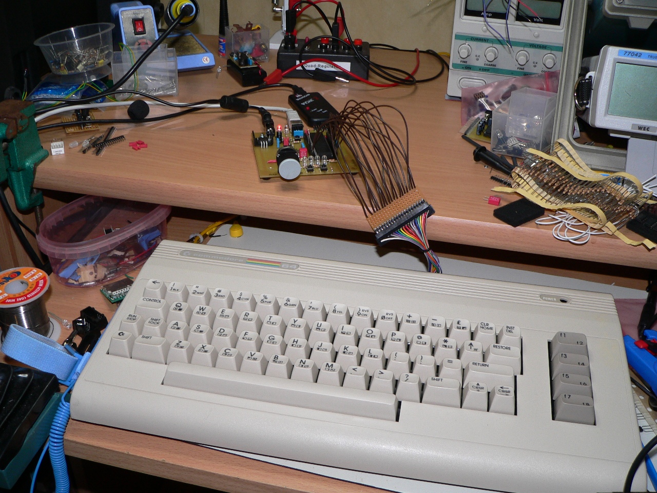
The reference board is useful because it acts as a ‘known working’ USB implementation (this is so you know that only your software is wrong when it doesn’t work – otherwise debugging USB code can be a little tricky).
In order to wire up the keyboard I used the following schematic taken from an on-line version of the C64 service manual:
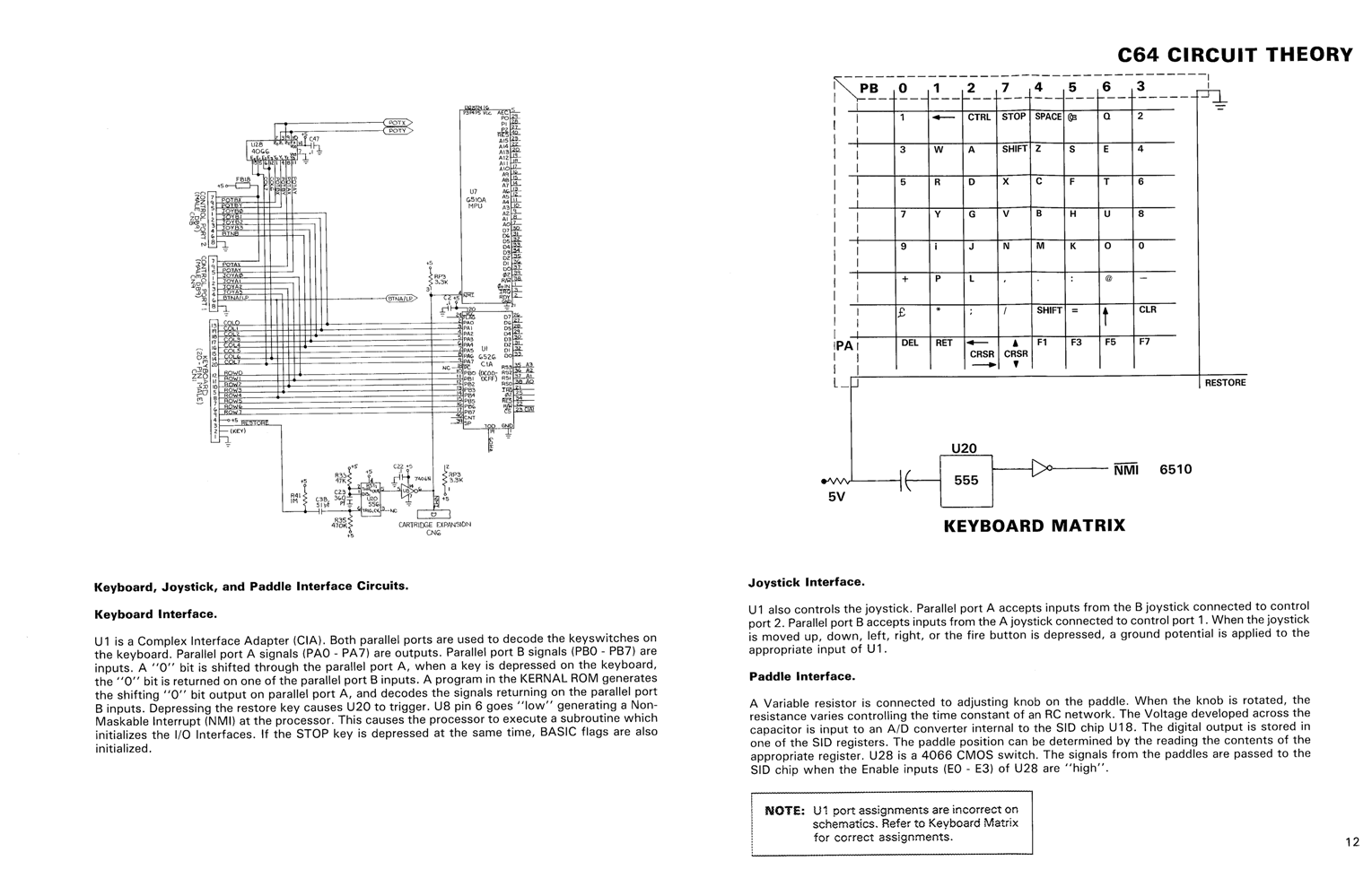
Once connected I was able to test the keyboard and the method for connecting it to the PIC. I also decided to test the configuration of the keyboard matrix since this is very important for detecting ‘ghost keys’ as you will see later in this article.
However, I was surprised to find out that the keyboard did not seem to match the schematic at all, when testing the matrix I saw ghost keys in the wrong places. Clearly, the C64 service manual was incorrect…
In order to confirm this suspicion I took the keyboard apart so I could manually reverse-engineer the matrix wiring. Firstly I took a picture of the PCB and then used photoshop to enhance the tracks on the board (a technique I used in my ‘reverse engineering the MB electronics Simon game’ project). This gave me the following image:
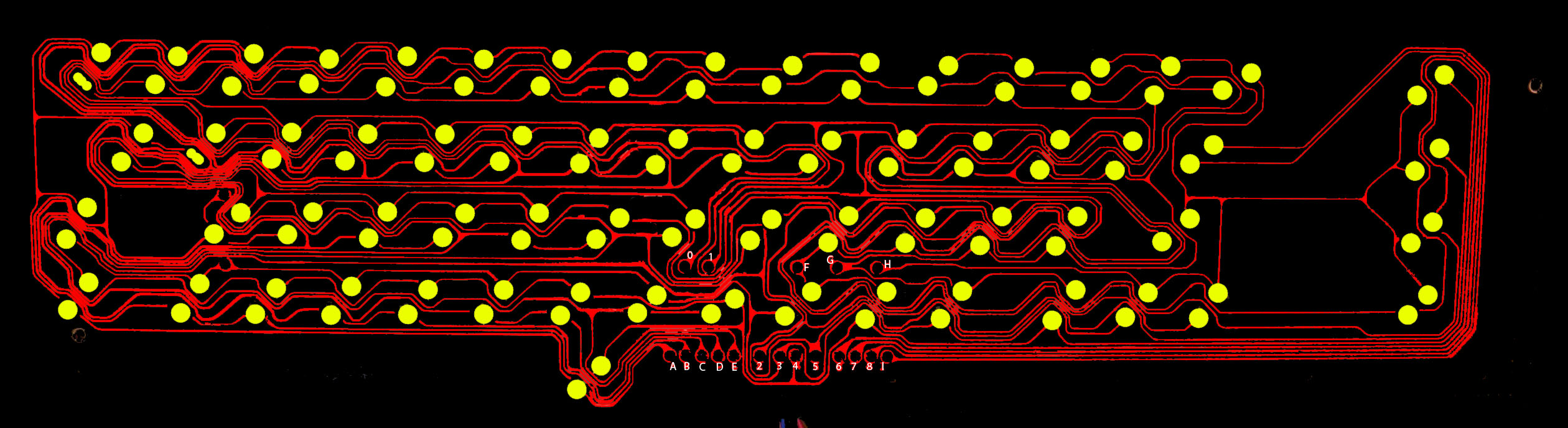
The next step is to trace the tracks on the PCB one by one (not a fun task!). For the record the following two diagrams (hand-drawn complete with crossing-out) show the physical wiring of the keyboard:
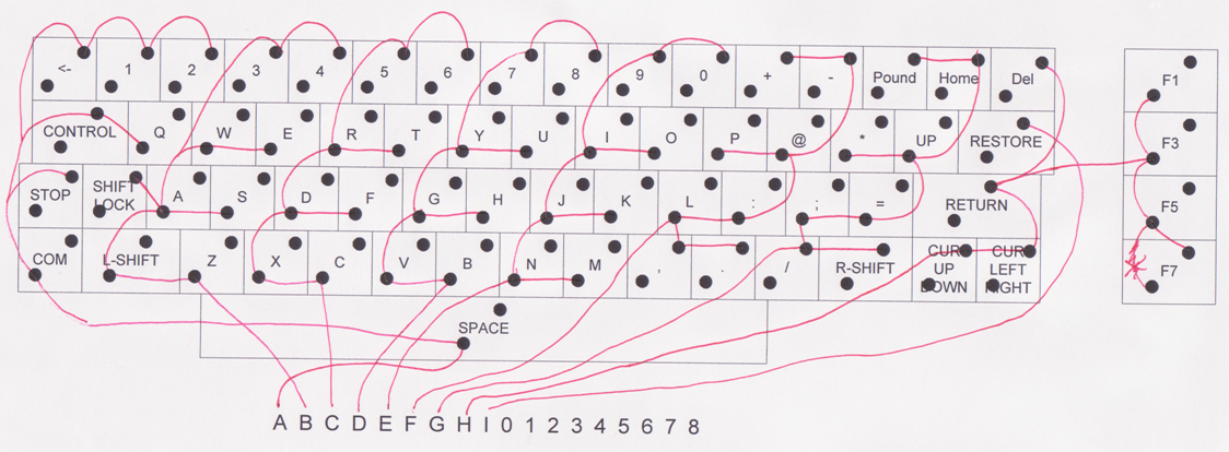
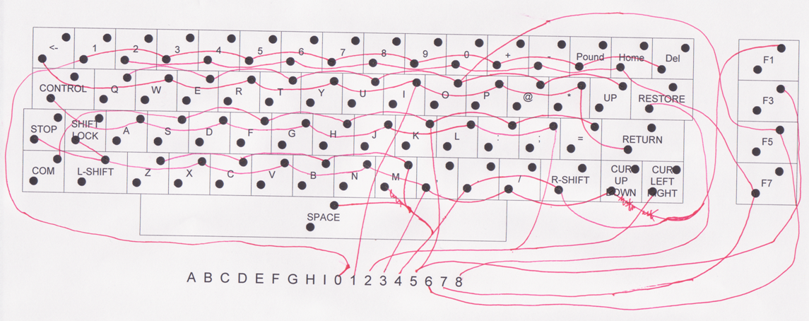
From the above diagrams you can clearly see that the letters marked on the PCB represent the columns in the keyboard matrix and the numbers represent the rows. Once I had the wiring mapped it was a simple case of tracing the wires from the keyboard back to the keyboard connector. This proved the initial analysis correct; the C64 service manual is incorrect. The following diagram shows my corrected keyboard matrix and keyboard connector pin out, by using this version I was able to confirm that the matrix wiring assumed by the test code on the PICDEM FS USB board was correct (I also added in the ‘key number’ to the matrix to help keymap coding and such like:
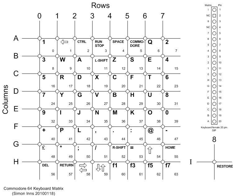
From this diagram it was easy to create a good circuit for the PIC. I used the 8-bit portD to act as the ‘sink’ for the columns and portB (with its internal pull-up resistors) for the rows. Making use of the internal weak-pull ups of portB saves having a bunch of external pull-ups.
Atari Joystick Interface
For the two joystick ports I used a similar design to my previous Atari Joystick USB Adaptor project. I simply took the circuit design and remapped it over the keyboard matrix connections (and also changed it from a PIC18F2550 to a PIC18F4550).
The joystick detection works by selecting the joystick to scan by setting either RA4 or RA5 to sink the current from the desired joystick and then scanning portB to see if any switches are pressed. This technique allows the keyboard and both joysticks to share the same portB pins (to take advantage of the built-in pull-up resistors) without getting any interference between the devices (i.e. a stuck joystick switch will not stop the keyboard from functioning – which is actually a real issue on the original C64 design).
Paddle Interface
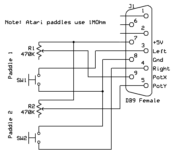
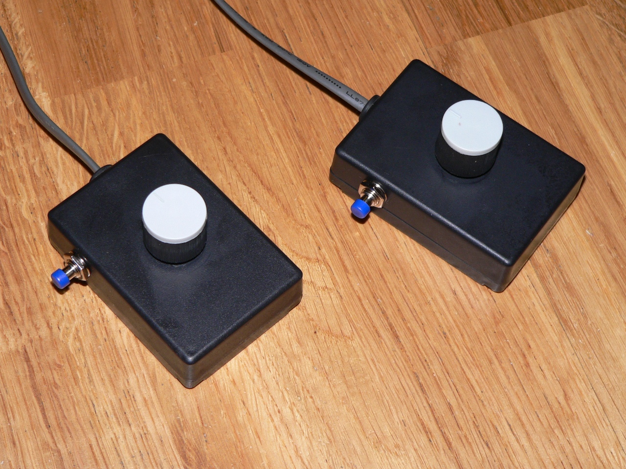
There are two types of paddles available with ‘atari style’ connections; the paddles from Commodore and the paddles from Atari. Unfortunately they are not the same. The Commodore paddles use 470Kohm potentiometers and the Atari paddles use 1MOhm. Since I didn’t have any original paddles I made some Commodore style paddles for testing purposes (making your own paddles is very easy to do, you just need 2 switches, 2 potentiometers (must be linear!), 2 boxes, some wire and a DB9 female connector). The paddles are connected according to the following schematic diagram:
The finished paddles mounted in boxes looked like this:
Originally I had intended to simply wire up the paddles to the PIC’s ADC ports, however after researching the paddle design it became apparent that it wouldn’t work. The PIC’s ADCs are designed to measure varying voltage, since the potentiometers in the paddles are only wired with two pins the potentiometer is not acting as a voltage divider (for this you would need the two outer pins of the pot. to be connected to 0V and +5V respectively, this would output a varying voltage on the wiper).
Since only two pins are connected on the potentiometer it is acting as a variable resistor (this is *not* the same thing). The PIC’s ADC would see 5Vs no matter what the position of the pot.
There are a few different methods of measuring the resistance of the variable resistor (effectively we need to measure the current supplied by the pot. not the voltage). The most common method is to use a capacitor which is discharged by the microcontroller and then the time for it to recharge (which is controlled by the amount of current supplied by the pot.) is measured. This method has a few disadvantages, firstly it is relatively slow; even using a 15pF capacitor the recharge time (with the pot. supplying minimum current) was 2-3 milliseconds which would slow down the scan rate of the device too much (there can be a maximum of 4 pots connected). Also this method is not easy to calibrate since the maximum and minimum timings are dependent on the tolerance/accuracy of both the pot. and the capacitor.
Another method is to connect the wiper of the potentiometer to ground via a resistor; since the potentiometer is supplied by 5Vs the resistor acts as the other ‘side’ of the voltage divider. This allows us to use the ADC of the PIC to measure a varying voltage. The advantages of this approach is that it is quick (as fast as the PICs ADC sampling rate) and easy to calibrate since the value at 0V and 5V is fixed. However, since one side of the voltage divider is variable and the other is fixed the output voltage is logarithmic not linear. This makes determining the potentiometer’s position more difficult.
To determine the position of the potentiometer using this method we need to do a little mathematics (not too much honest!). Consider the following voltage divider circuit:
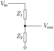
To calculate the output voltage (Vout) from this circuit we need to use ohm’s law which states Vout = (Z2 / (Z1 + Z2)) * Vin, for example, if Vin is 5Vs and Z1 and Z2 are 10Kohms then Vout would be (10000 / (10000 + 10000) * 5V) which equals 2.5V. Now since we know the value of Z2 (which is whatever fixed resistor we choose) and the value of Vin (which is 5Vs) it’s possible to transform the formula to express it in terms of Z1 (i.e. to give us the value of the variable resistor Z1)…
Z1 = ((Vin / Vout) x Z2) – Z2
Since Z1 is a linear potentiometer with the range of 0-470Kohms we have our linear measurement back again… nose bleed anyone? 🙂
Since the ADC reads 1023 at 5Vs we can use the ADC maximum value to represent 5Vs then the formula will work (since the Vin will be voltage in from 0-1023), this will give us an output of 0-470000 which we then simply divide into a range of 0-255 for the USB HID position value.
Since the value of Z2 isn’t too important (except for the calculation) I used a value of 100Kohms since this makes the calculation easier to perform. The only other issue is that, due to the logarithmic nature of the input voltage to the ADC we need to measure some pretty small and close values. Since the pot. and power supply to the pot can ‘jitter’ quite a bit, this can cause the paddle to move around due to the ADC accuracy and the power fluctuating. To prevent this there is a small capacitor connected in parallel with the Z2 resistor to smooth out the input. The bigger the capacitor, the smoother the input, however the charging-time of the capacitor slows down the speed at which the ADC reacts to movement. Since super-high speed is not necessary in this application a 220nF capacitor is a good compromise between smoothness and response time.
If you decide to use Atari paddles (with 1Mohm pots.) you will need to alter the calculation in the code as appropriate, but there is no reason why they shouldn’t work using this method.
As a final note, the 100Kohm fixed resistors also act as pin pull-downs, this will make it easy to detect if a paddle is connected to the port (the ADC result will always be a stable 0Vs when nothing is connected).
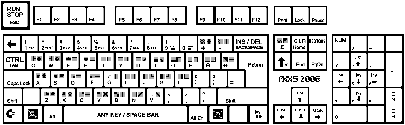
Keyboard LED
The original C64 has a low-intensity red LED power indicator in the top-right of the keyboard. Since this was a standard 5mm LED I decided to replace it with a tri-colour LED (capable of showing red, green and yellow) to use as a status indicator.
Circuit Schematic
All of the above information and research lead me to the following circuit diagram which is based on my PICDEM FS USB and my joystick adaptor combined with the keyboard and paddle hacking documented above:
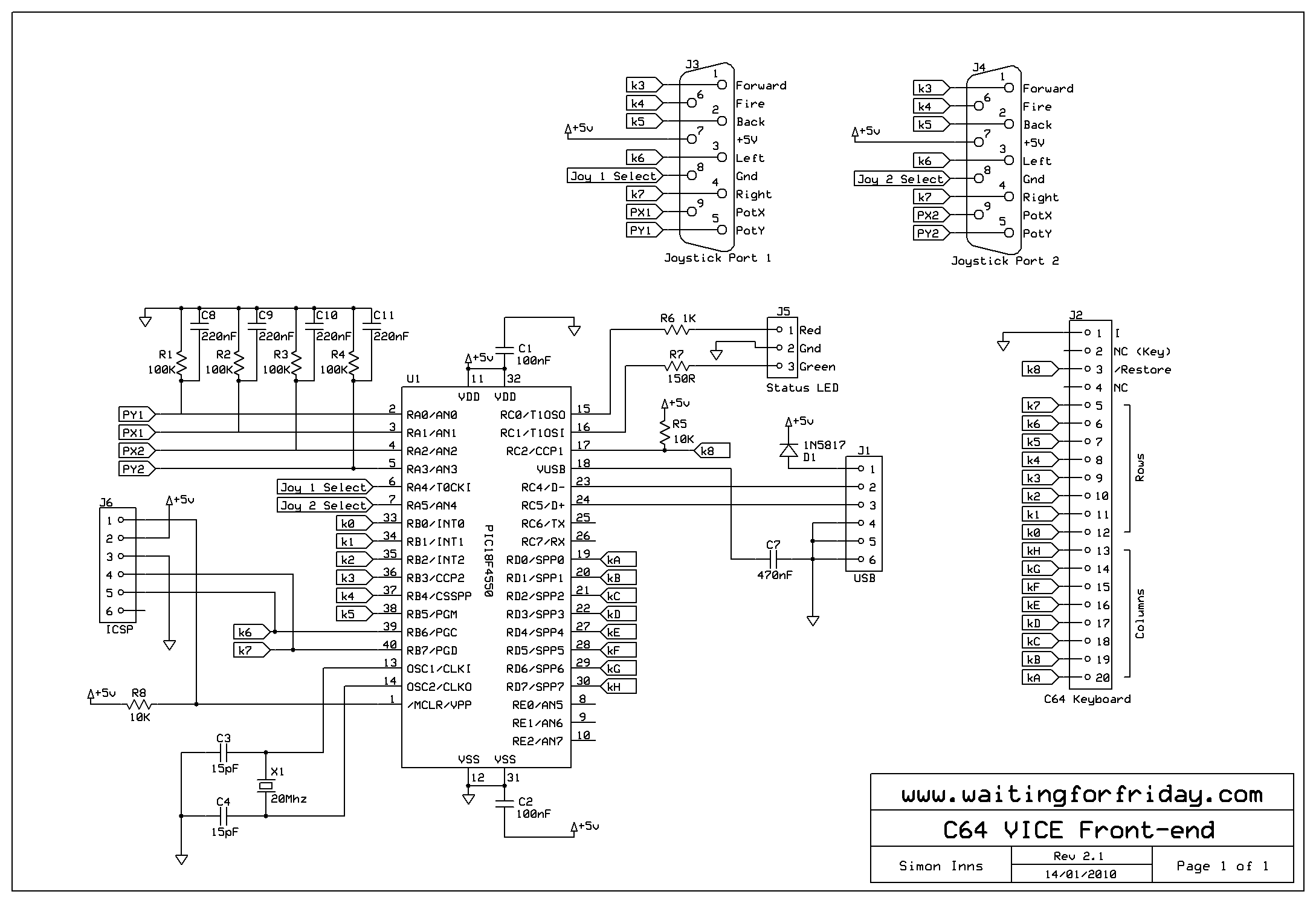
As you can see from the diagram the USB adaptor is bus-powered and does not require external PSU. Care should be take that any devices connected to the +5V power supplied by the joystick ports do not exceed the maximum ratings for the USB bus.
I decided to use a PIC18F4550 since I needed quite a few pins to interface all the hardware. The alternative would have been to use external multiplexing of the ports but this would require more ICs making the circuit more complex. Given the price difference between a PIC18F4550 and a PIC18F2550 the bigger chip was the better choice.
The RESTORE key is connected to the microcontroller with a pull-up resistor (since it connects to earth when pressed).
The only ‘compromise’ I made on this board was to use RB6 and RB7 to connect to the keyboard matrix. This means that the keyboard/joystick detection will not work correctly when a PIC programmer is connected (the programmers tend to pull-up the pins), however this will not affect the final design since no programmer will be connected anyway.
Hardware design and assembly
PCB design
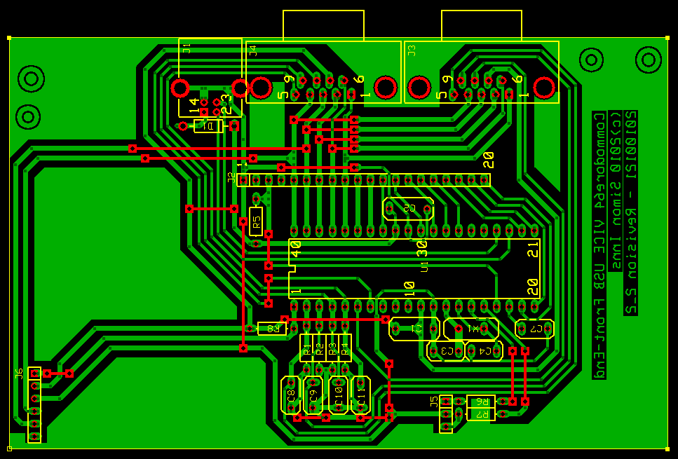
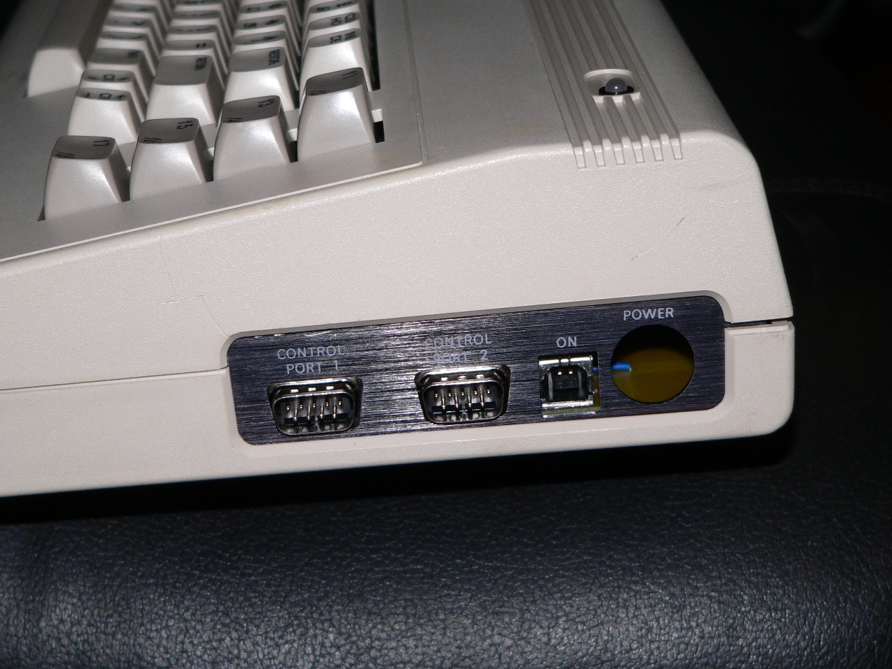
I wanted the adaptor to fit in the original case without modification, so I measured up the existing ports and the screw-holes in the plastic case. I decided to use the square hole where the original power switch was located for the USB b-type plug (since it was exactly the right size). The PCB also needed to have mounting holes for the metal port cover on the original machine.
I also extended the board slightly to place the ICSP programming header in the middle of the original expansion port slot on the back of the case. This isn’t really necessary, but I thought it would look neater.
Here is the final PCB artwork drawn in expressPCB:
Assembly
In the following picture you can see the board mounted inside the C64’s case. The board is held in place by the two screws either side of the side-ports. A small self-adhesive rubber foot is used to even out the board on the left-hand side (since to reach the next set of screw-holds would have required extending the board by several inches):
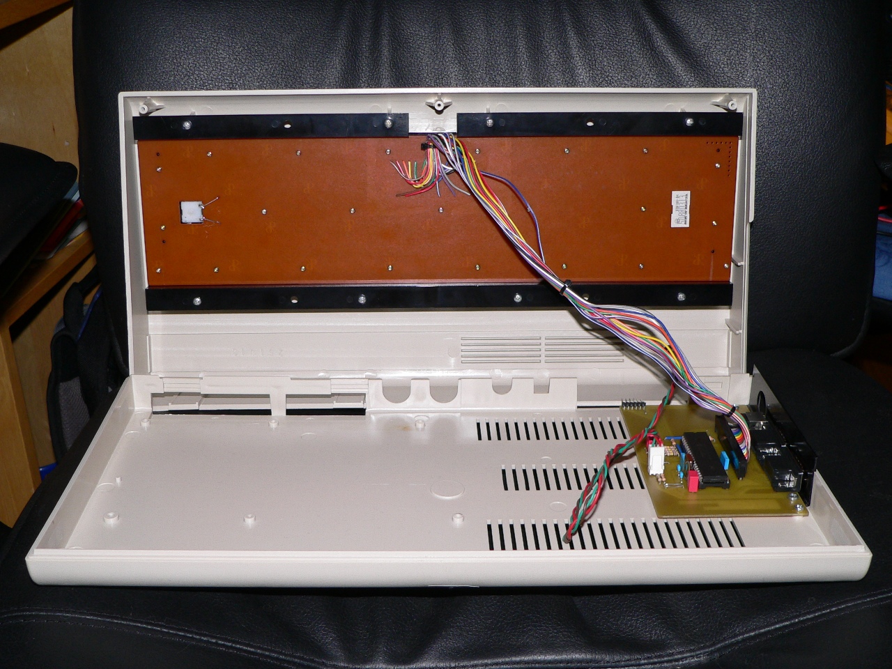
The alignment of the board is pretty close to the original. If you have problems lining the board up you can simply increase the radius of the screw-holes in the PCB to allow you to move the board slightly before fixing it in place:
Once the board is in place you can screw the C64 case back together and the hardware is complete. All programming can be performed with the case closed since the ICSP header is accessible through the expansion port slot in the back of the case (I deliberately shortened the PCB to ensure that the programming header does not extend beyond the case to prevent it being bent or damaged when not in use). Of course, if you are not planning to do any development on the adaptor board you can omit the ICSP header.
Software
Keyboard Interfacing
The keyboard interface is broken up into several steps:
- Read the raw keyboard switch states into an array by scanning the keyboard matrix
- Perform a ghost-key blocking algorithm
- Perform debounce on all keys
- Map the detected keys to a USB HID compatible keymap
- Send the key-press information over the USB to the host
Reading the raw keyboard
To read the keyboard switches the PIC simply ‘sinks’ the correct column through portD and then scans the rows on portB to see which keys are depressed. This is then stored in an array by the software. The RESTORE key is connected separately from the main keyboard matrix so it is processed independently and stored as the 65th key on the keyboard.
Ghost-key blocking algorithm
All matrix-based keyboard are susceptible to ‘key-ghosting’. This is caused when at least 3 keys are pressed with 2 of the keypresses in adjacent rows, if the 3rd keypress occurs in the same row as one of the adjacent keypresses a fourth key is ‘ghosted’ (i.e. you press 3 keys, the computer sees 4). I’d be the first to admit this isn’t a very clear explanation (!) but there are plenty of sites you can Google which explain this with clear diagrams.
The software looks at the raw keyboard switch state for potential key-ghosts and, if detected, drops all 4 keypresses. This is obviously not an ideal situation, but it’s unavoidable without physically modifying the keyboard to place diodes in-line with the switches.
Keyboard debounce
The keyboard debounce removes the ‘electrical noise’ from the keyswitches by waiting for 5 scans with the keyswitch in the same state before setting the key to on or off. The software debounces the keyswitches both on and off to give the most accurate response from the keyboard.
Keymapping
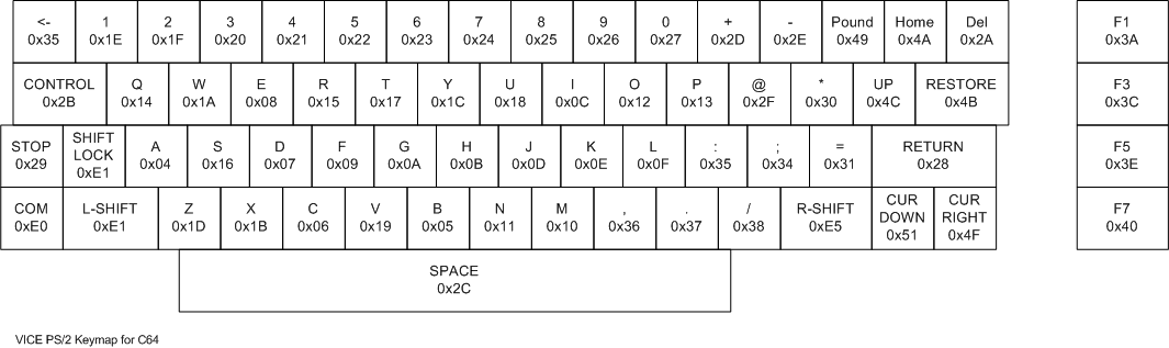
The keymapping is a little unusual since the device is designed to work with VICE. The first issue is that the HID keyboard protocol is designed for mapping standard PS/2 keyboards; since the C64 keyboard has key-configurations which aren’t supported by the PS/2 map the software cannot directly support the C64 keymap.
However VICE is designed to work with a normal PC keyboard so it maps the original C64 keyboard positionally onto the PS/2 keyboard layout. This results in the following keymap (from the VICE knowledge base):
So, in order to work properly with VICE the USB adaptor needs to map the C64 keys to the same PS/2 keys as used by VICE, then VICE maps them back to the C64 keymap in the emulator. This is a round-about route, but works flawlessly. By following the PS/2 keycodes available from the web and the VICE diagram above we get the following keymap for the USB adaptor:
The disadvantage of this route is that the C64 keyboard is not very useful for typing outside of the VICE emulator (unless you touch type, since the keymap layout is very close to a real PS/2 keyboard). It should be possible to use a ‘magic key combination’ on the C64 keyboard to cause the USB adaptor to switch keymaps, however I’m saving this feature for version 2 since a modern keyboard is a lot more comfortable for general purpose usage 😉
Sending the keypresses over USB
The USB HID keyboard protocol allows for a maximum of 6 simultaneous keypresses plus modifier keys (CTRL, SHIFT, etc.) and the USB adaptor software supports this fully. The exception to this is when a pattern of keys is pressed which causes a potential ghost-key (since the blocking algorithm will remove the keypresses). I’ve made the software simple to modify if you don’t want the ghosting detection, simply comment out the call to the procedure, however this will make it very hard to type at any speed on the keyboard.
Joystick Interfacing
The joystick interface is much simpler than the keyboard. The USB adaptor simply supports two independent HID game controllers and maps the X and Y directions of the joysticks to the HID devices. Since VICE has support for standard PC joysticks this works perfectly.
Paddle Interfaces
For the paddle interfaces we have to read the ADC value from the PIC and then perform the mathematics described above to get a paddle position between 0 and 255. The code looks like this:
calc = (((1.023 / ((float)adcResult/1000.0)) * 100.0) – 100.0) * 0.60;
if (calc > 255) calc = 255;
calc = 255 – calc;
Firstly we do a floating-point calculation to get the value of the variable resistor, to make the numbers a little easier to work with everything in the calculation is ‘pre’-divided by 1000 (remember the comment above about using a 100Kohm Z2 resistor to make the calculations easier?). The result is then multiplied by 0.60 giving us a result in the range of about 0 to 280, this is to give a little ‘headroom’ for variances in the potentiometers. Then the result is range-checked and inverted ready to be sent via USB.
Since the raw ADC value will be zero if no paddle is connected (the 100Kohm fixed resistor acts as a pull-down when no paddle is connected) this is used to switch the adaptor between digital joysticks and analogue joysticks (with the X and Y supplied by the two paddles). If a paddle is detected the left and right joystick switches are used for the 2 fire buttons (following the Atari/Commodore wiring scheme).
Unfortunately VICE 2.2 seems to have very little support for paddles at the moment, however other emulators do allow you to use proportional joysticks, so this feature is working, but pending better VICE support 🙂
Device measurements and test
Power consumption
By splicing a USB cable and placing a multimeter in-line with the USB bus power cable it is possible to monitor the power consumption of the device when running. Fully configured and with a TAC2 joystick and two paddles connected the power consumption was 49-51mA (bus powered devices must be <100mA). This leaves around 25mA spare per joystick port which should be more than adequate.
Keyboard, Joystick and Paddle Scan Speed
The polling loop of the device executes approximately once every 2 milliseconds, giving an effective scan speed of 500 times a second (this was measured by pulsing a processor pin every loop and then measuring the output with an oscilloscope). With the default debounce of 5 loops this means the keyboard is updating 100 times a second… fast enough for even the most furious of typing!
Code size
The complete code is just under 9K (8740 bytes). Plenty of space left for adding additional features and other customisations.
Files for download
Please review this site’s Creative Commons licence before downloading any content.
MPLAB Project zip file containing the source code:
C64_Keyboard_and_Joystick_Adaptor
ExpressPCB and ExpressSCH files of the PCB and circuit diagram:
You can also download my original Hi-Tech C18 port of the Microchip USB stack from Hi-Tech’s forums (ported by myself and Richard Stagg):
Here is the pre-compiled hex file for the project:
C64 Keyboard and Joystick Adaptor Hex
To-do / Ideas
- USB Suspend is not honoured: To be fully USB 2.0 compliant the device must enter a low-power suspend mode when the host requests. The call-back event handler is present in the USB stack but I haven’t added any suspend code yet (Windows and Linux work flawlessly anyway).
- Caps / Num-lock indication: The software is capable of receiving these events, but no code is included to show the status
- Multiple keymaps: It should be possible to support multiple keymaps and allow a ‘magic key combination’ to switch between them. One for VICE and one for general usage would be nice.
- Paddle smoothing: Given that the scan rate is so high, it would be good to put some smoothing for the paddles into the software, they can still be a little jittery in certain positions.
Hi, I need the file to program the PIC directly with the ICProg, thanks.
I’ve added this to the article download section for you.