Acorn BBC Master and Electron Cartridge Breakout
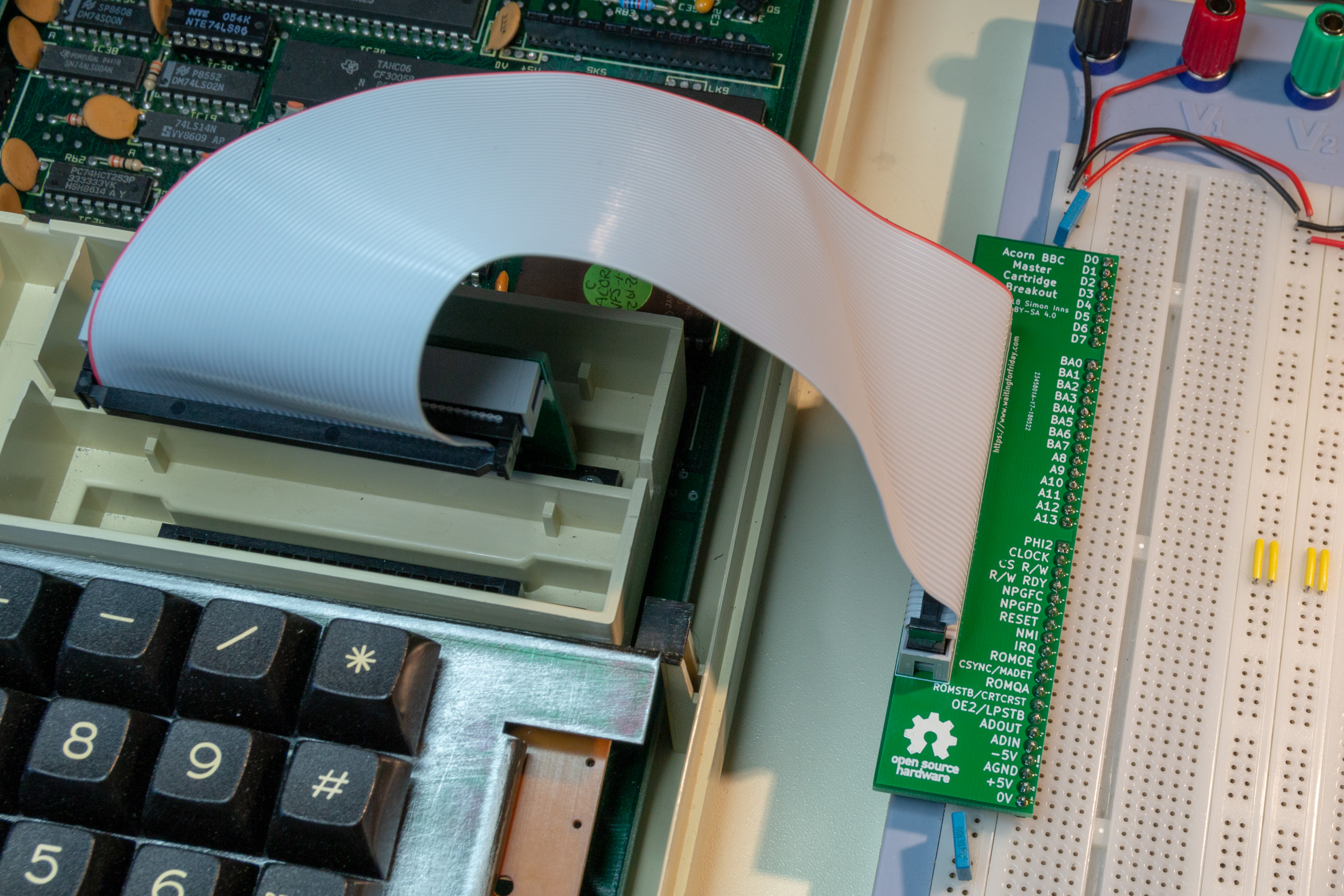
This project provides a simple breadboard adapter/breakout board for prototyping cartridges for the Acorn BBC Master and Acorn Electron 8-bit computers. The design consists of two PCBs, the first plugs into the computer’s cartridge slot and the second is designed to plug along the edge of a standard 2.54mm pitch breadboard. The two boards are […]
SmallyMouse2 – Universal USB to Quadrature Mouse Adapter
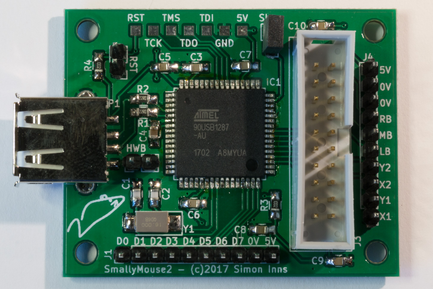
SmallyMouse2 is a universal USB to quadrature mouse adapter for many 8-bit and 16-bit retro computers and allows the use of modern USB mice on machines such as the Acorn BBC Micro, Acorn Master, Acorn Archimedes, Commodore Amiga, Atari ST and many more. Unlike most existing mouse adapters, SmallyMouse2 implements a fully USB compatible interface […]
60W Acorn BBC Master power supply upgrade
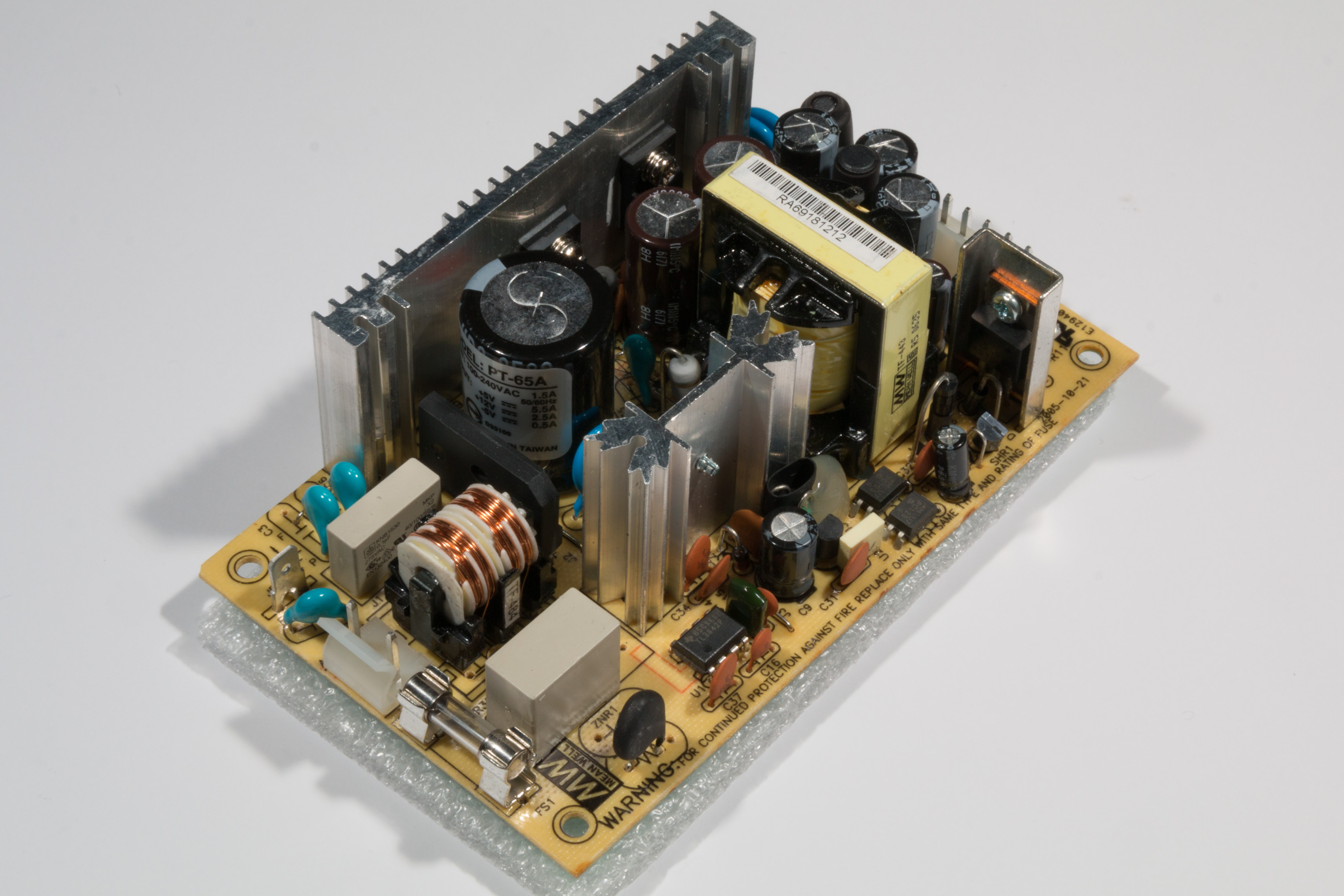
The Acorn BBC Master 128 computer (and variants such as the Turbo and 512) come with a 35W switched mode power supply unit. For general use the power supply is sufficient, however for applications where more peripherals are required or for machines where the power supply has failed, this project demonstrates how to fit a […]
A new look for the website!
Regular visitors to Waiting For Friday will notice some big changes to the website. Gone is the old Mediawiki based site and, instead, a shiny new WordPress site has taken its place. In addition, the forums have now been replaced by a built-in commenting system that allows both the articles and the comments to be […]
USB to Quadrature Mouse Adapter
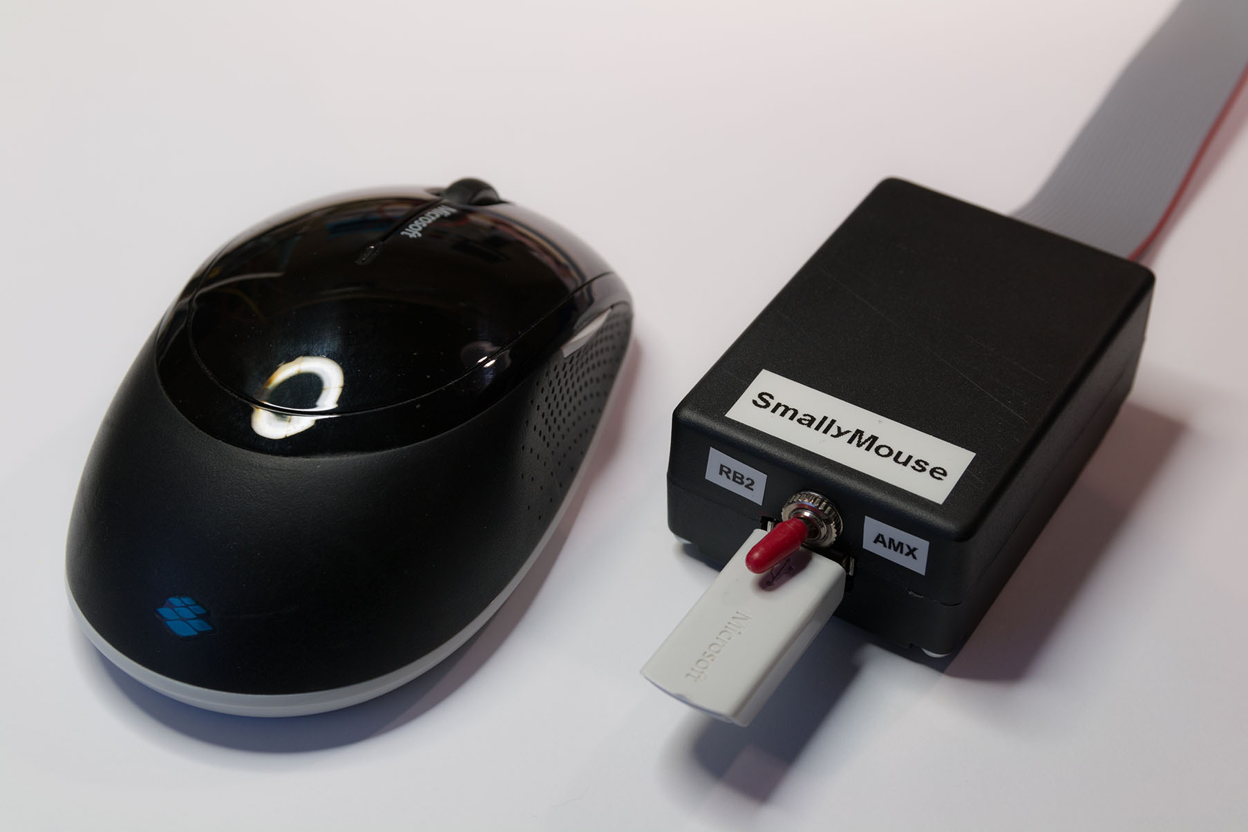
SmallyMouse is a project that creates a USB mouse adaptor for 8-bit Acorn computers including the BBC Micro and Master series machines. SmallyMouse can emulate the two most popular user-port mice made for the BBC – the AMX mouse and the Marconi RB2 trackball (as used in the BBC Domesday project) and provides a small […]
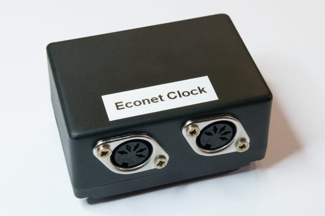
Acorn Econet Clock V2
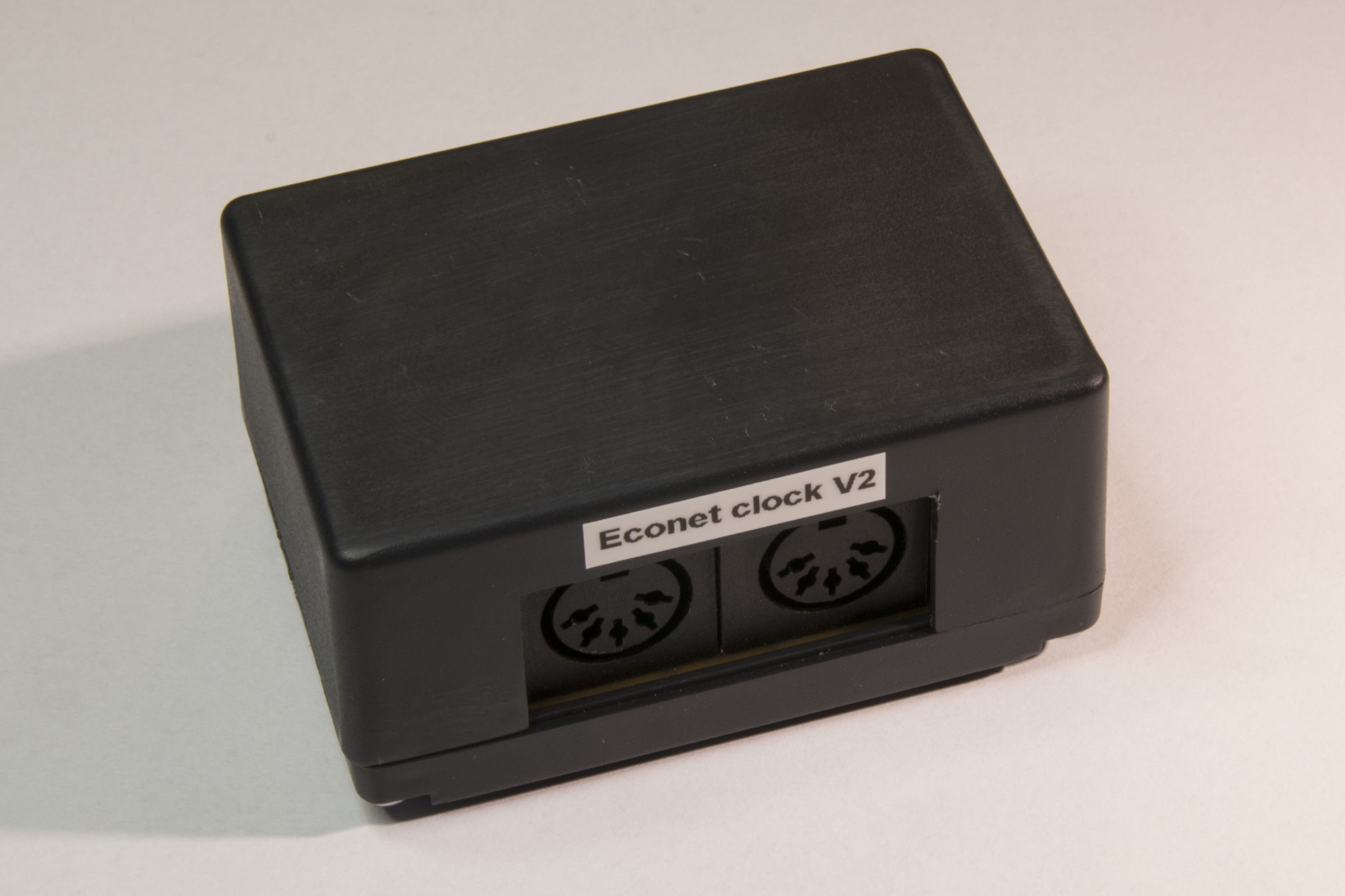
Continuing on from my first Acorn Econet Clock project, I received some good feedback and advice from other Acorn enthusiasts and decided to make a slightly more complex version 2 of the clock. The original design was simplistic enough to be built on stripboard however, this revised design is built on a custom PCB with […]
Acorn Speech PHROM TMS6100 Emulator
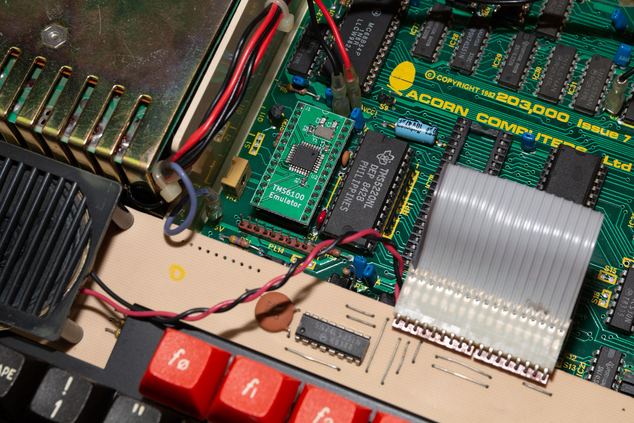
This project creates a TMS6100 speech PHROM (PHrase Read Only Memory) for use with the TMS5220 Voice Synthesis Processor in an Acorn BBC Microcomputer. Whilst it’s still possible to purchase TMS5220 ICs from sites like Ebay, the TMS6100 was a mask-programmed ROM that Acorn produced specifically for their speech upgrade and is therefore difficult and […]
Acorn Econet Clock
This project creates an Acorn Econet clock suitable for use with Acorn computers from the 1980s and 90s. The Acorn Econet network is an EIA-422-B based network that is driven by a differential clock signal. In the network topology the clock generator is a separate unit that is daisy-chained into the network bus and ensures […]
Fast Hartley Transformation Library for AVR microcontrollers
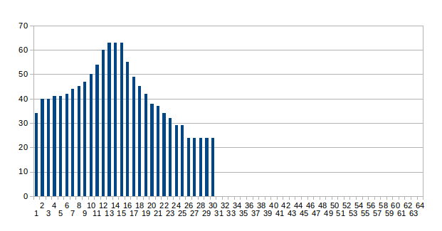
This article demonstrates an implementation of Fourier transform known as the ‘Fast Hartley Transformation’ or FHT. The FHT is very similar to the more popular FFT however it operates on a real number input (where-as the FFT requires a complex number input of both real and imaginary parts). The primary reason to use FHT over […]
Nintendo Four Score USB
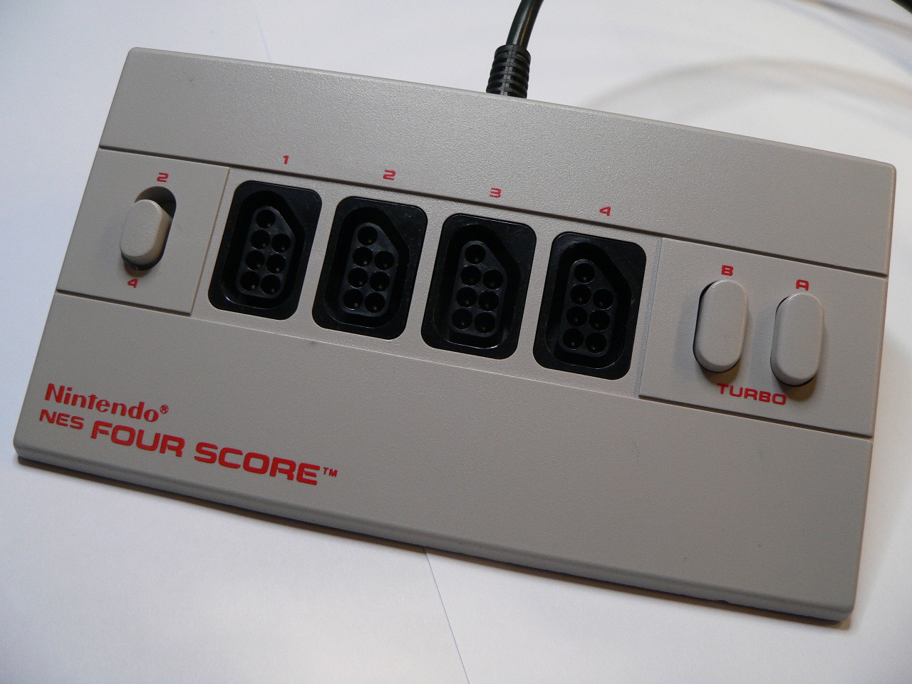
The Nintendo Four Score is a 4 port joystick adaptor for the original 8-bit NES console which allowed you to plug in 4 joysticks (or ‘joypads’) and play compatible 4 player games. Since my daughter wanted to play some of the NES classics such as Zelda and Mario Bros. I decided to purchase on of […]