Nintendo Four Score USB
Contents
The Nintendo Four Score is a 4 port joystick adaptor for the original 8-bit NES console which allowed you to plug in 4 joysticks (or ‘joypads’) and play compatible 4 player games. Since my daughter wanted to play some of the NES classics such as Zelda and Mario Bros. I decided to purchase on of the adaptors from ebay and convert it into a 4 port joystick adaptor for USB.
The circuit board used in this article is a drop-in replacement for the original PCB; you simply remove the major components from the original board (the joystick connectors and switches) and solder them back in to the new board. The new board allows you to reassemble the Four Score without changing the look of the device. Even the turbo buttons and the 2/4 player switch is reconnected and functional.
The replacement board and firmware provides 4 HID compliant joysticks which work under Linux, Mac or Windows. All of the buttons are de-bounced on and off to give a solid feedback during game-play.
Hardware
Schematic
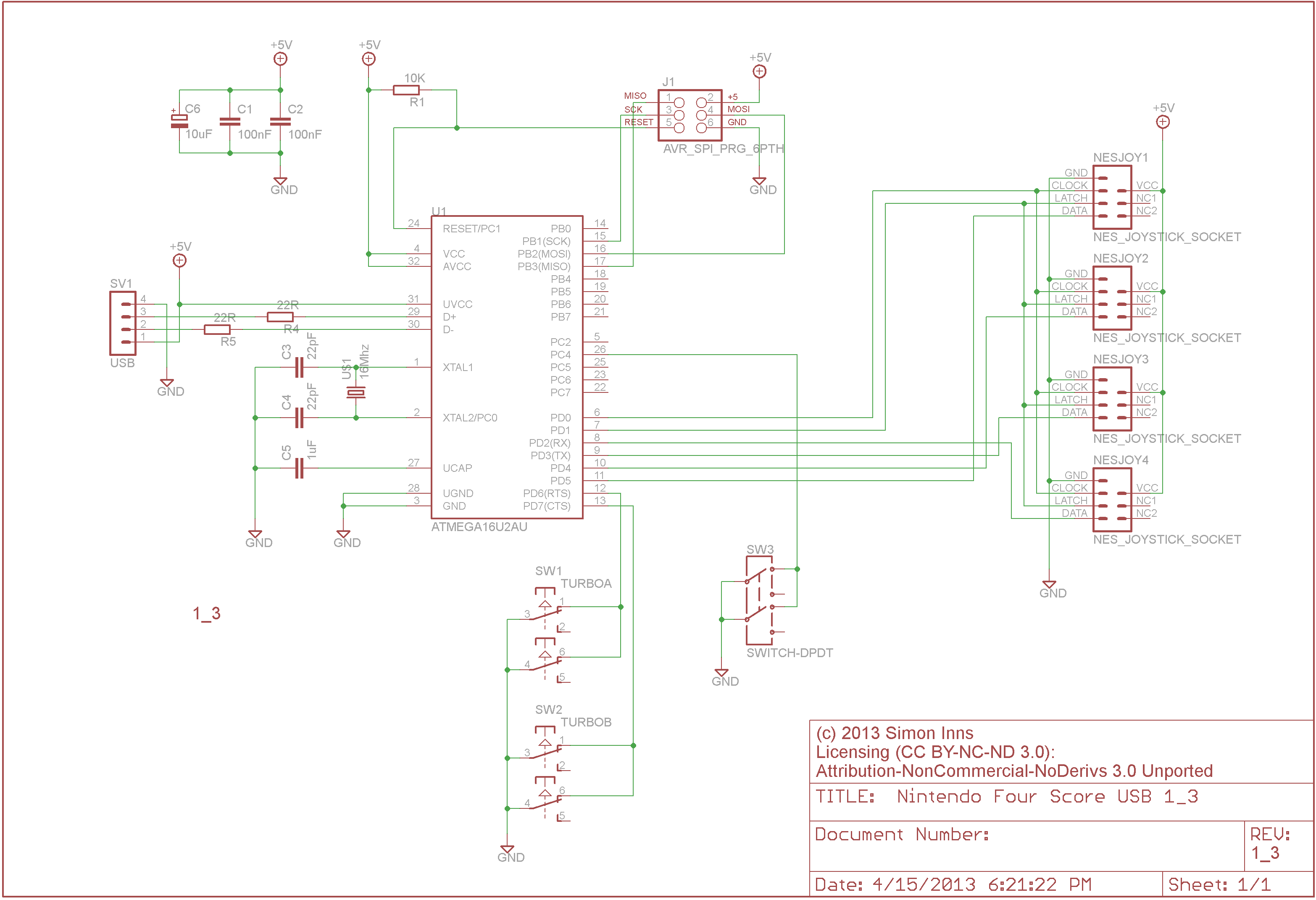
The schematic for the Four Score USB is based on the Atmel ATmega16U2 microcontroller which is easily adequate for the task and has an on-board USB transceiver. The joystick ports all share clock and latch lines which allows the microcontroller to latch the controller data, poll the clock and then read all 4 joystick states in one go. Apart from the 16Mhz clock and the standard required USB hardware the microcontroller is connected to the four joystick ports, the DPDT 2/4 players switch and the 2 Turbo buttons. The design also includes an ISP programming header to make flashing the device firmware easy. The finished schematic is shown below (and is available for download in Eagle CAD format at the bottom of this article):
PCB Design
Since the new PCB needed to fit exactly in the same place as the original PCB it was important to measure and recreate the original board closely so that all of the switches and ports lined up when fitted into the case. The first step was to strip all of the components from the original board to allow it to be measured accurately:
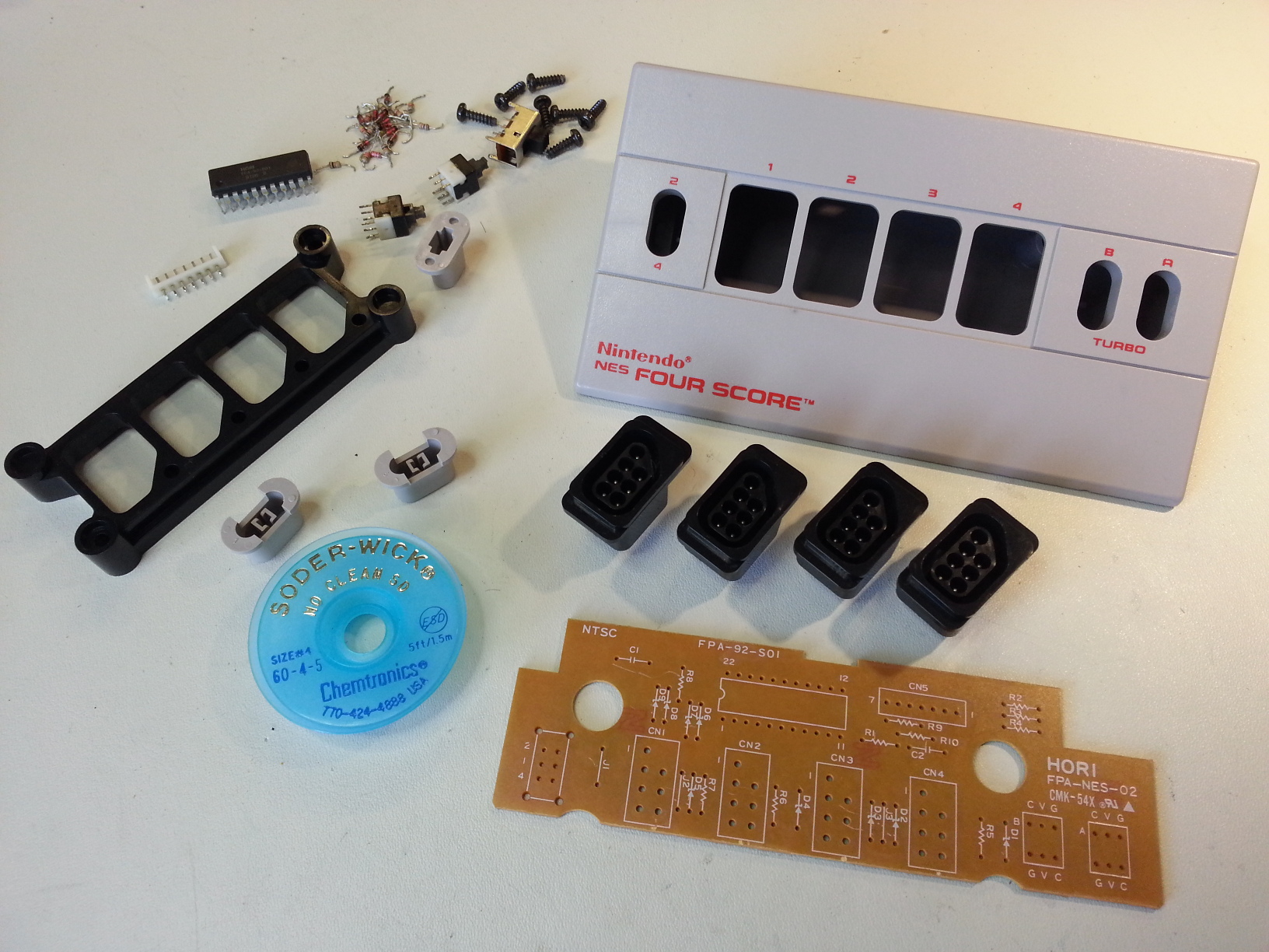
The easiest way to remove the various components is to use a wide-tip on your soldering iron and some de-soldering braid (which is also shown in the picture above). The braid allows you to cleanly remove the solder from the board and then you simply prise the parts out. Once the board was stripped and measured the boards dimensions and the placement of the major components was drawn in Eagle CAD starting with drawing the component foot-prints based on the measurements of the removed joystick ports and the three switches. The measurements and alignment could then be tested by printing the board design onto transparency sheets (such as those used for overhead projectors) and then the sheet can be overlaid on the original board to check everything is in the right place.
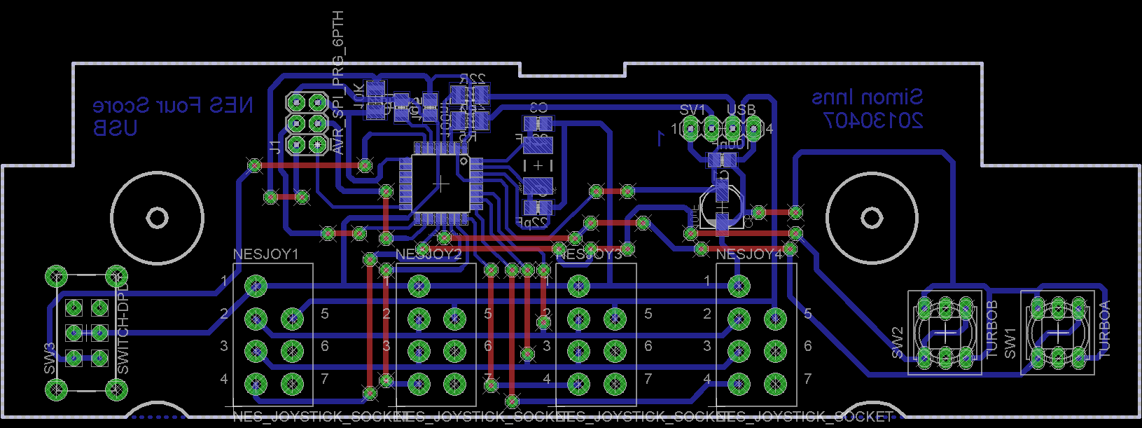
Once the component layout and board dimensioned were correct the rest of the required components are added resulting in the PCB design shown below:
Populated PCB
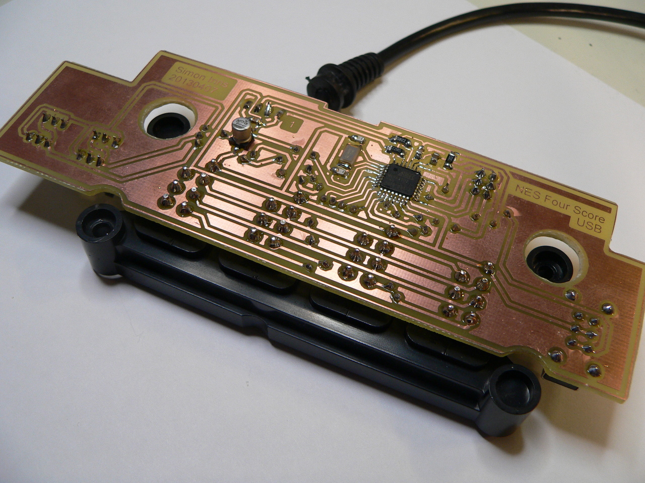
The PCB is designed as a single-sided PCB to make it easier to produce. All of the surface mount components are mirrored in Eagle so that they are mounted on the underside of the board. The board is assembled by starting with the wire-links, then the SMT components and then finally the switches and ports from the original board. Here is a picture of the underside of the board after assembly:
Firmware
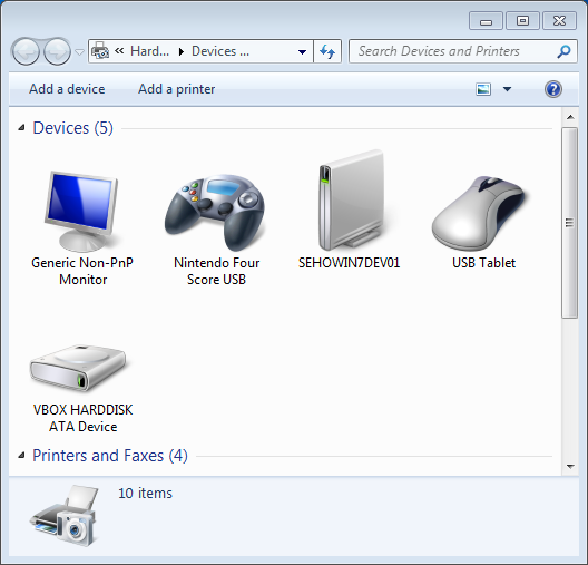
The firmware project can be downloaded from the bottom of this article and contains a GPL licensed firmware project which can be opened in Atmel Studio 6. The firmware is based on the LUFA USB library and implements a composite USB device with 4 separate joystick HID interfaces. The joystick device can be seen in ‘devices and printers’ under windows 7:
Right clicking on the Four Score USB device and selecting ‘Game Controller Settings’ will show the four available game controllers which are in order of ports 1 to 4 on the device itself. If you select the first device and click on properties you will see the following window:
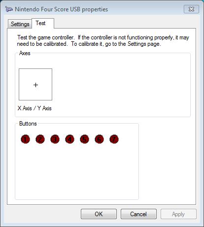
The button mapping is as follows:
- Fire A
- Fire B
- Select
- Start
- Four Score Players 2/4 (on when 2 is selected)
- Four Score Turbo A
- Four Score Turbo B
Note that this mapping is only for the first joystick. For joysticks 2-4 there are only 4 buttons representing the joystick buttons.
The firmware function is quite easy to follow; it scans the four score buttons and then scans the buttons for each one of the joysticks. There is then a simple de-bounce procedure (de-bouncing switches helps to ensure the the button is fully pressed before it sends an ‘on’ to the computer – since mechanical switches can be noisy the ATmega may receive a number of random on/off results before the button is completely pressed or released). The rest of the firmware is involved in detecting when the host requests a HID report for a joystick and then sending the joystick report back.
Conclusions
The Four Score USB interface is a great hit; I fitted the unit with a 4m USB cable which allows the kids to sit comfortably on the sofa and connect the interface to the HTPC (modern LCD TVs allow you to sit a lot further back than the original TVs the games were designed for). My HTPC is running Ubuntu and the interface is very easy to map as controllers for the emulator. Once the kids have finished with the Four Score it is nice and small, so it’s simple to store until the next retro gaming session. The biggest advantage with the design is that the joysticks are all original controllers and since the alteration is all in the Four Score the original controllers still function with the NES console.
Files for download
This zip file contains both the AVR Studio 6 firmware project files for the project:
This zip file contains both the Eagle CAD project files for the project: