Building a Robot Arm
Contents
This article shows how to build your own robot arm constructed mainly from 2mm aluminium. Although it is possible to buy ready-made robot arm kits they tend to be expensive and quite small; I wanted to see if it was possible to make a good quality 6 DOF (Degrees Of Freedom) arm from aluminium bars and sheets using fairly basic workshop tools (no CNC, no 3D printer and no laser cutters).
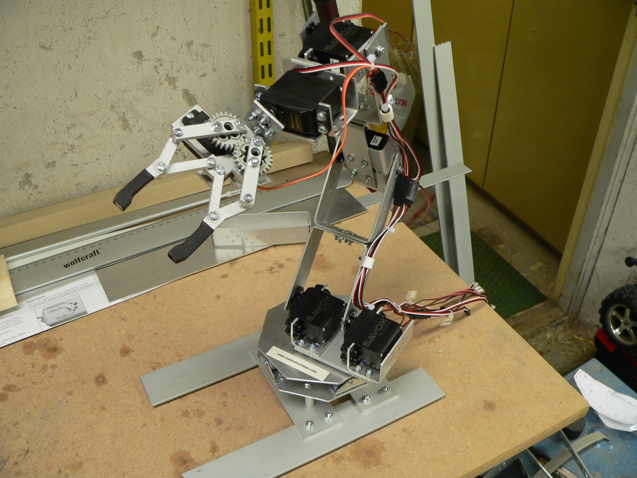
The completed robot arm
The mechanical design of the arm is based around 2 universal bracket designs along with a number of smaller brackets. The pivoting parts are made from standard hobby servos and small flanged bearings in order to keep the design as simple as possible.
In order to help show the construction of the arm in as much detail as possible each part is covered by a separate section below. If anything is unclear you are welcome to ask for more details in the comments.
All of the parts were designed in libreCAD (an open-source 2D CAD package) so you are welcome to install the CAD and reuse the plans which can be downloaded below. If you are curious about the CAD files and don’t have libreCAD installed I have also included a PDF version of the plans in 1:1 scale. As an example of the diagrams here is a (not to scale) image of the servo bracket design:
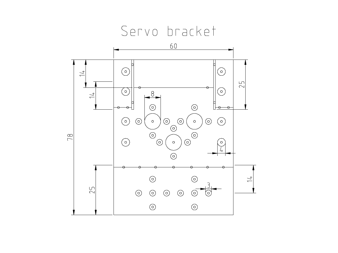
PNG of the libreCAD servo bracket design
Constructing the robot arm
Building the servo mount bracket
The servo mount bracket is made from a sheet of 2mm aluminium (I sourced a 500mm x 500mm sheet from elfa.se in Sweden, however you should be able to get similar sizes from your local hardware store). Since you will need 5 of these brackets it is a good idea to build a template and a jig to help making them easier and more consistent.
All of the parts of the robot arm are made using very similar techniques so, for this first bracket, I will show as much detail as possible for the construction.
To make the template I used a 60mm x 1000mm x 4mm aluminium bar which was cut using a mitre-saw to ensure it has a square edge. The bracket template is then printed out and cut to size using a sharp hobby knife and a metal ruler.
To line up the template on the material I first put a small amount of paper glue on the back of the template (the paper glue common for crafts is perfect such as Pritstick). This allows you to line up the edge of the template with the aluminium without it moving around too much. Once lined-up the template is then held in place by wrapping strips of sticky-tape over the template until it is completely covered:

Servo mount template positioned aluminium ready for drilling
Once prepared you then dot-punch the template at each of the marked punch points. This makes it a lot easier to drill the template accurately as without the dot-punch marks the drill tip will slip on the surface of the aluminium.
The idea of the template is to allow you to both drill through and dot-punch through (for the fold-lines) so you need to make sure that the drill-size is wide-enough for your dot-punch to go through without being too wide and making the template inaccurate. I used a 2.5mm drill bit.
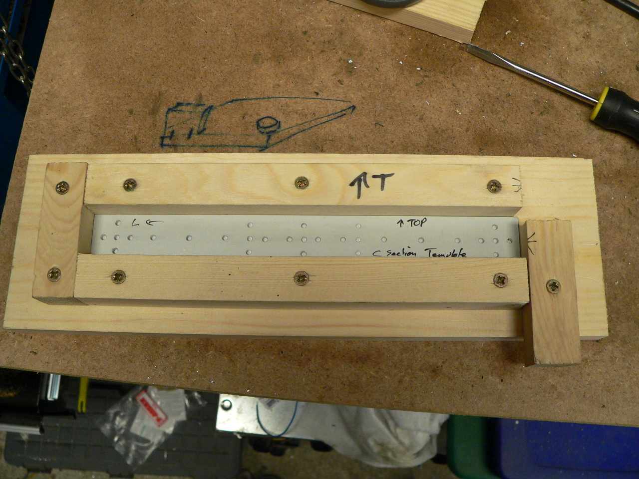
Once the template is drilled you will then need to make a simple jig out of scrap wood to hold the template in place. To make the jig simply line up 4 pieces of wood around the template and fix in place using some wood screws. You will want to leave some small gaps around the jig to allow you to get the drill in place when using the template:
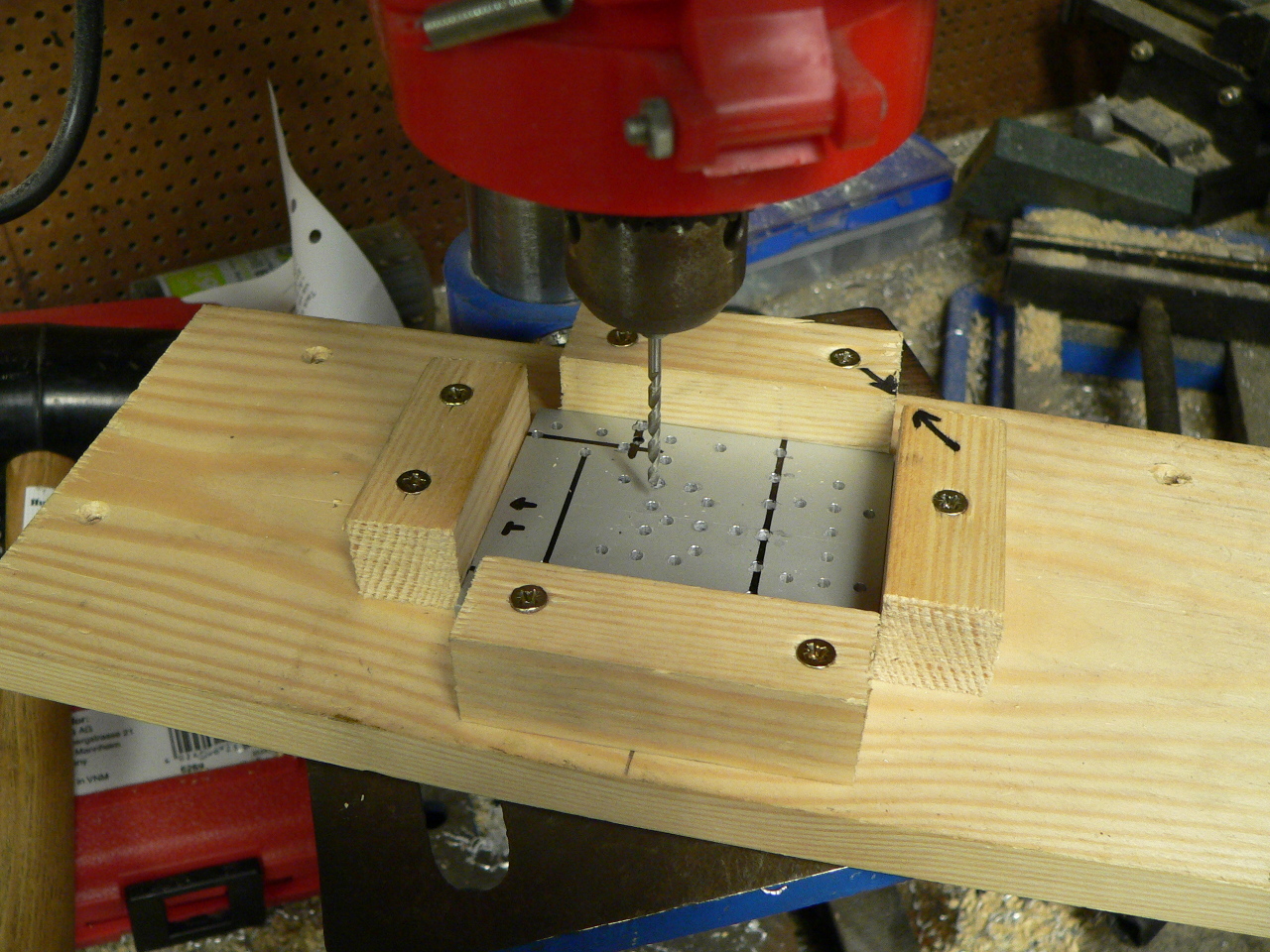
Servo mount bracket jig
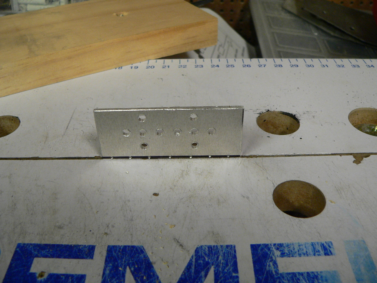
Now that you have the jig and template you simply have to cut a piece of 2mm thick aluminium to size (I used a combination of the mitre saw, jigsaw and file to do this). Place the aluminium in the jig with the template on top and start by dot-punching the markers and fold-lines shown on the template. After that use a bench drill to drill the guide holes for the rest of the bracket.
Now take the aluminium out of the jig and drill the guide holes to the correct size as shown in the CAD drawing. When drilling thin aluminium you will find that the underside of the drill holes can burr quite a lot. To remove the unwanted burring you can either use a de-burring bit or you can use a drill-bit which is much larger than the original hole (for example an 8-10 mm drill bit for the 3 mm holes).
To make the folding easier I also used a square ruler to mark the fold-lines according to the dot-punched lines:
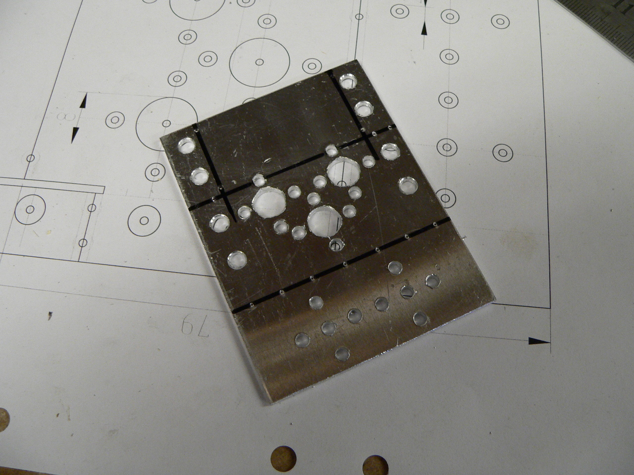
The servo mount bracket before folding
Before folding the aluminium you will first need to saw the two lines at the top of the bracket. Saw them down to the dot-punched marks. To fold the bracket place it into a vice (a wood-working vice works best as it doesn’t mark the surface of the bracket as much as a metal vice):
Servo mount ready for bending
Line up the fold-line and then place a piece of wood over the bracket. Fold it back by pressing on the wood. This helps to keep the pressure even over the bracket and bend it without warping the shape. You can use the edges of the wood to bend back the smaller parts in a similar manner.
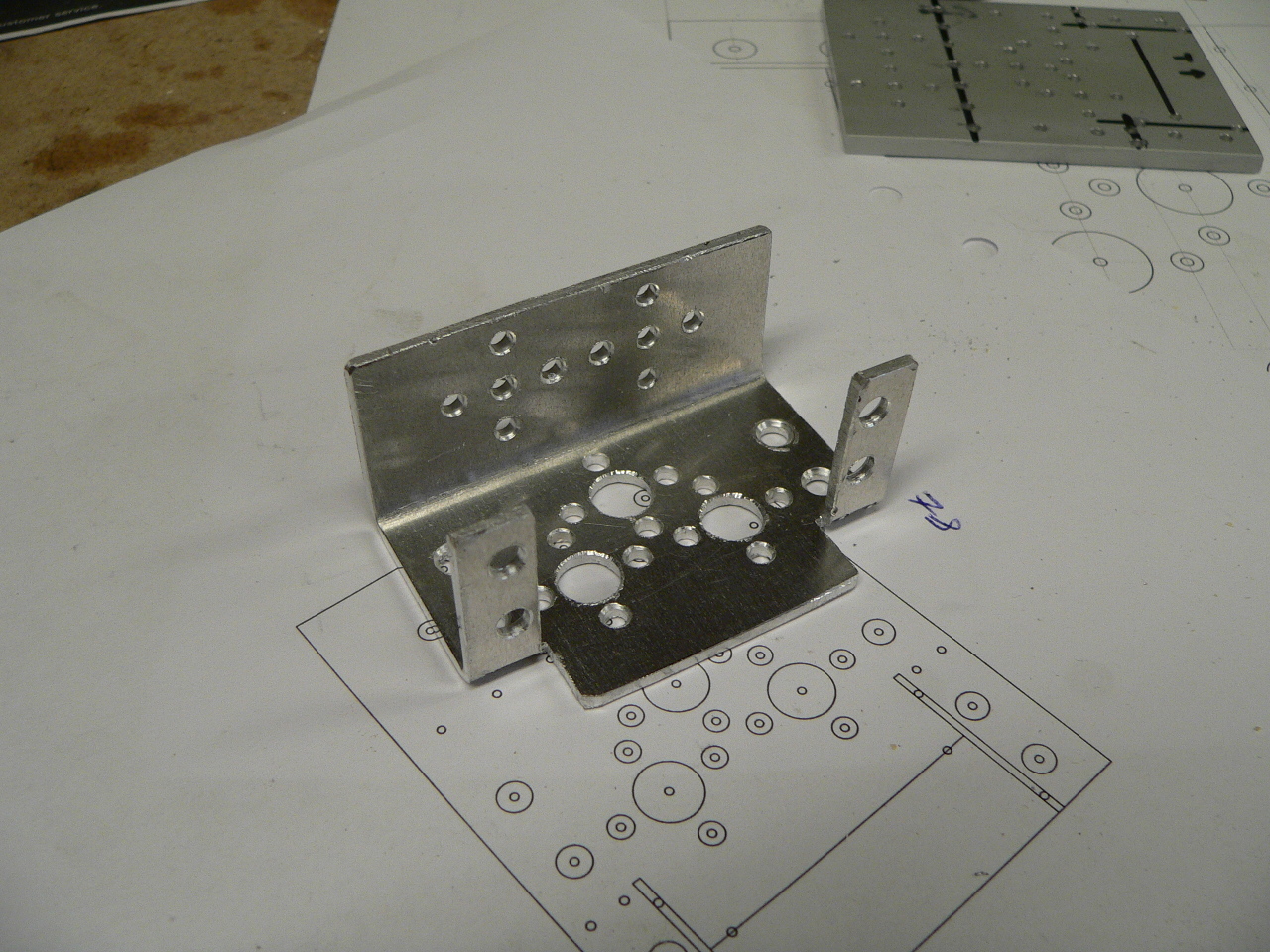
Once you have finished bending the bracket use the template and a ruler to mark a cut line across the front of the bracket and then saw off the unwanted material:
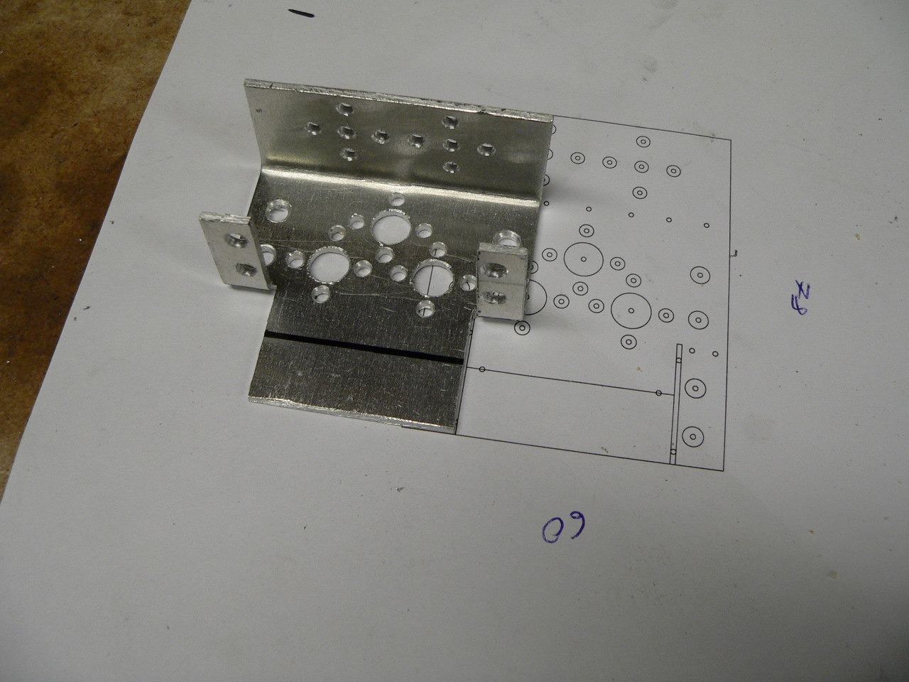
The servo mount after bending
With the bracket all cut and ready it’s a good idea to go over the bracket with a file and smooth out any sharp or rough edges. If you want to remove any nicks or scratches from the surface of the bracket you can rub over the bracket using fairly course wire-wool. This gives the bracket a nice ‘brushed’ finish. The final bracket should look similar to the following:
The finished servo mount bracket
Building the C-bracket
The C-bracket is made in an almost identical manner to the servo mount bracket. Here I used 25mm x 1000 mm x 2mm aluminium bars for both the template and the brackets themselves. Just like the servo mount bracket you first cut the aluminium to size and then glue and sticky-tape the CAD template over the top. Dot-punch the material and then drill the template with 2.5mm holes (or the best size for your dot-punch to go through). The finished template and jig should look similar to the following:
C Bracket template and jig
Once the bracket is drilled in the jig take out the part and re-drill the holes to the correct sizes as shown in the CAD drawings. Take care when bending the bracket to make sure you bend each on in the same manner. You will need to make at least three of these brackets for the robot arm:
Finished C brackets
Building the L-brackets
The robot arm has 3 different L shaped brackets for the mid-arm, the wrist and the end-effector mount. Since these brackets are all different sizes there is no need to make a jig and template. Simply cut the aluminium to size (they all use the 25mm x 1000mm x 2mm bar) and tape the CAD drawings over the cut bars. Dot-punch the template and then drill the pieces directly.
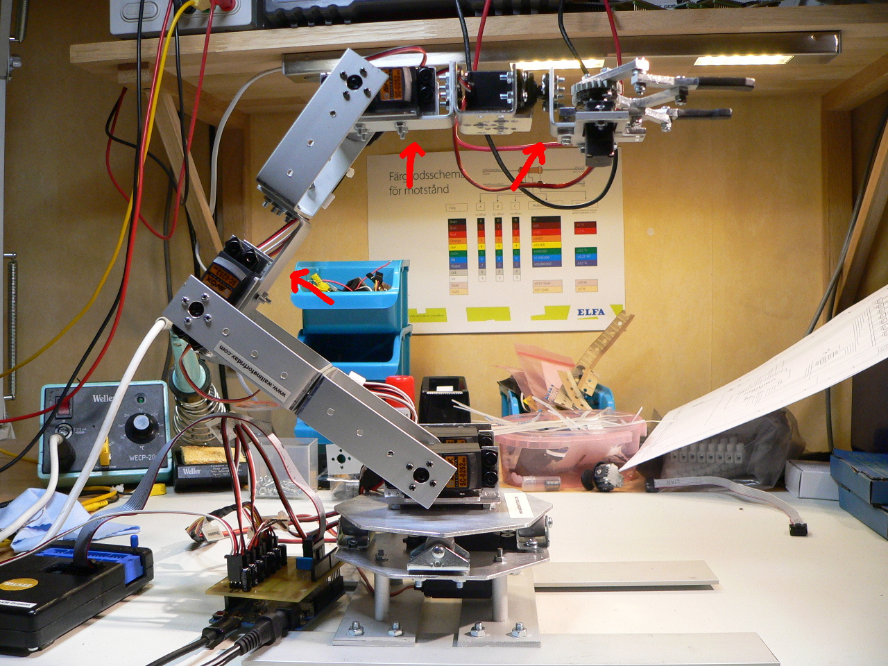
Picture showing the location of the L brackets
Building the turntable
As the robot arm is relatively heavy the bottom servo needs plenty of support in order to rotate the arm smoothly. To achieve this the arm is mounted on a turntable which is supported by four casters that relieve the servo of the weight placed laterally across the servo which, unsupported, could easily twist the servo apart and damage it.
The base of the turntable is made in a similar manner to the brackets. The printed CAD template is placed over the sheet of aluminium and held in place using sticky-tape. The cut and drill pattern is then dot-punched into the material. Once the paper is removed use a steel ruler to mark out the cut-lines:
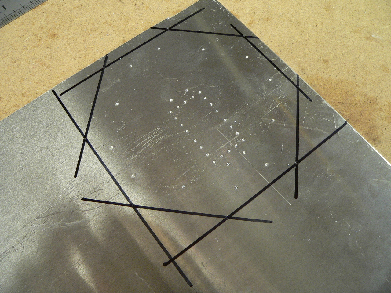
Turntable base uncut
The resulting shape is then cut from aluminium using a jigsaw and then filed into shape. Note the rectangular pattern in the centre of the part. This is a drill pattern for cutting out the aluminium so that the servo can be fitted through. This part is drilled and then cut out with a Dremel before being filed into shape so that the servo fits easily in the slot.
To support the upper rotating part of the turntable there are four small furniture casters placed around the outside of the part. The casters are 30x17mm with 15x14mm rollers. These are pretty common items and can be purchased from most big hardware stores. The casters are attached to the base using M4 screws and nuts.
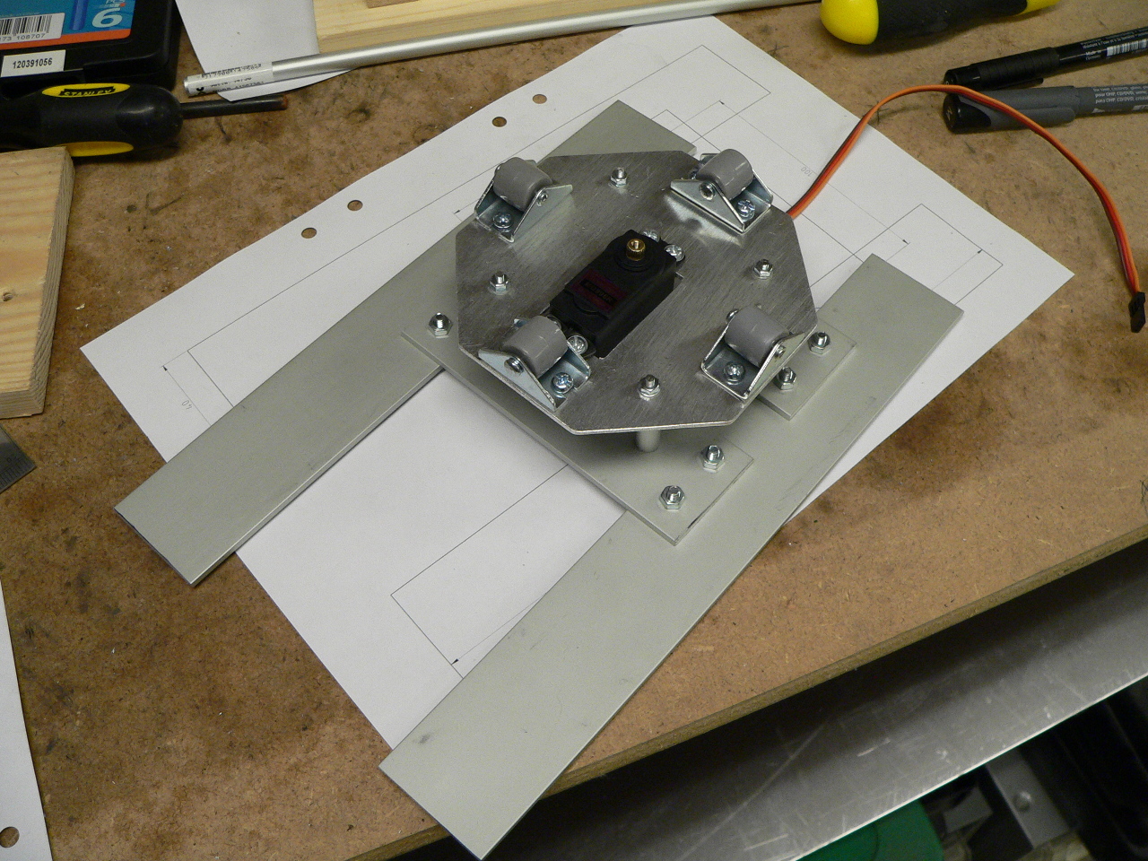
Once the servo and casters are mounted the lower turntable should look like the following picture:
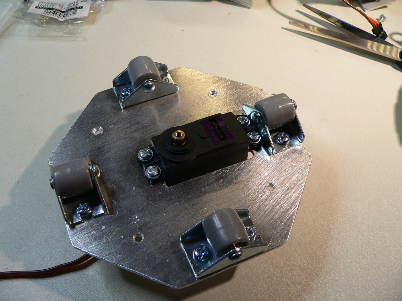
The completed turntable base
The turntable base is then attached to four pieces of aluminium cut from a 40mm x 1000mm x 2.5mm bar. Again the dimensions and drill pattern is included in the CAD drawings.
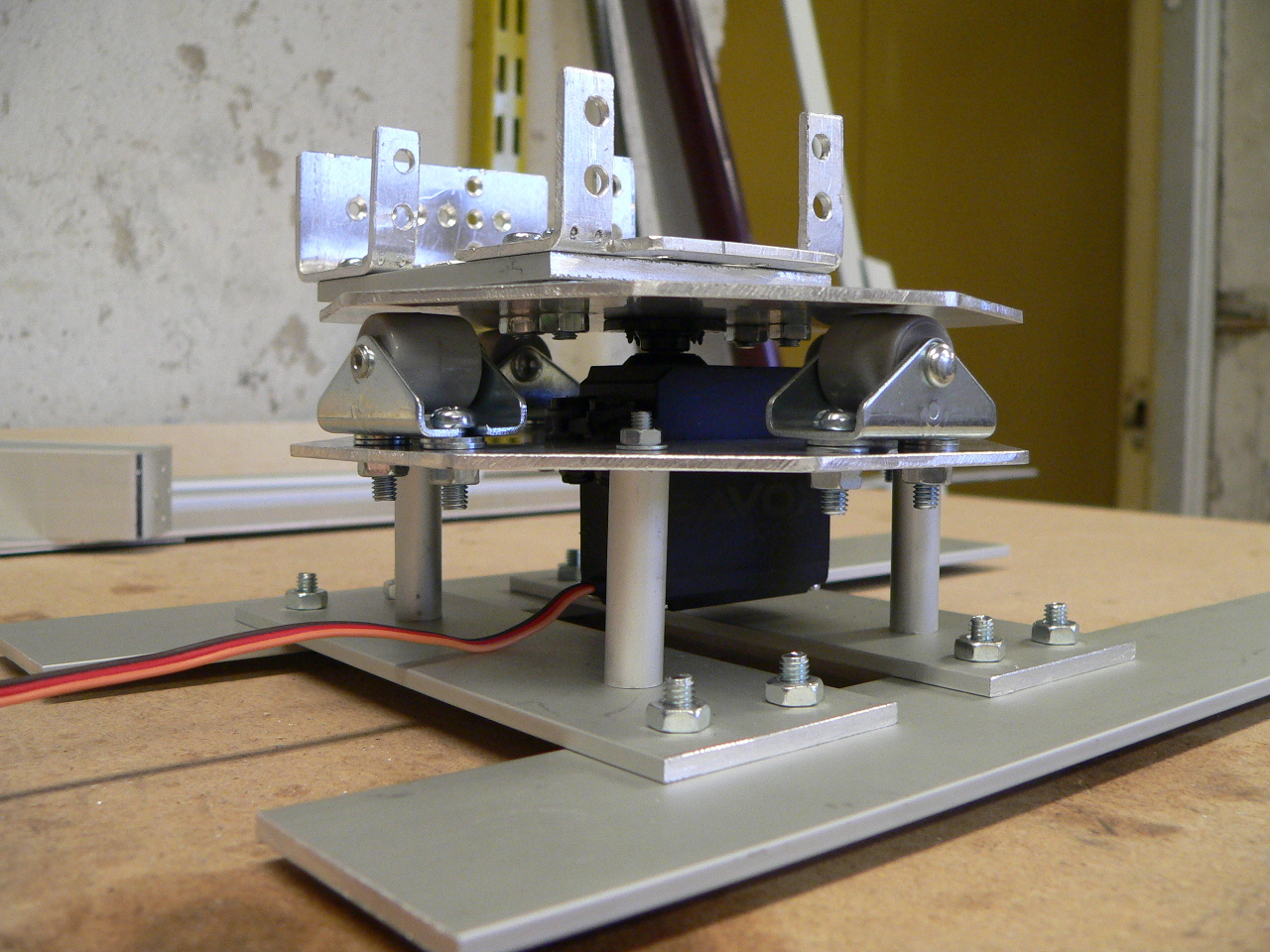
To attach the turntable to the foot of the robot there are 4 aluminium tubes (8mm tube with 1mm thickness) cut to 30mm lengths. These are held in place by some M3 threaded rod which is cut to length and then bolted at both ends. Note that the foot is not sufficient to hold the robot arm when fully extended to one side (it will overbalance). The final arm will need to be secured to a heavier flat surface, however I wanted to be able to stand the arm up whilst working on the assembly. The turntable base and foot is shown in the following picture:
Turntable base and foot
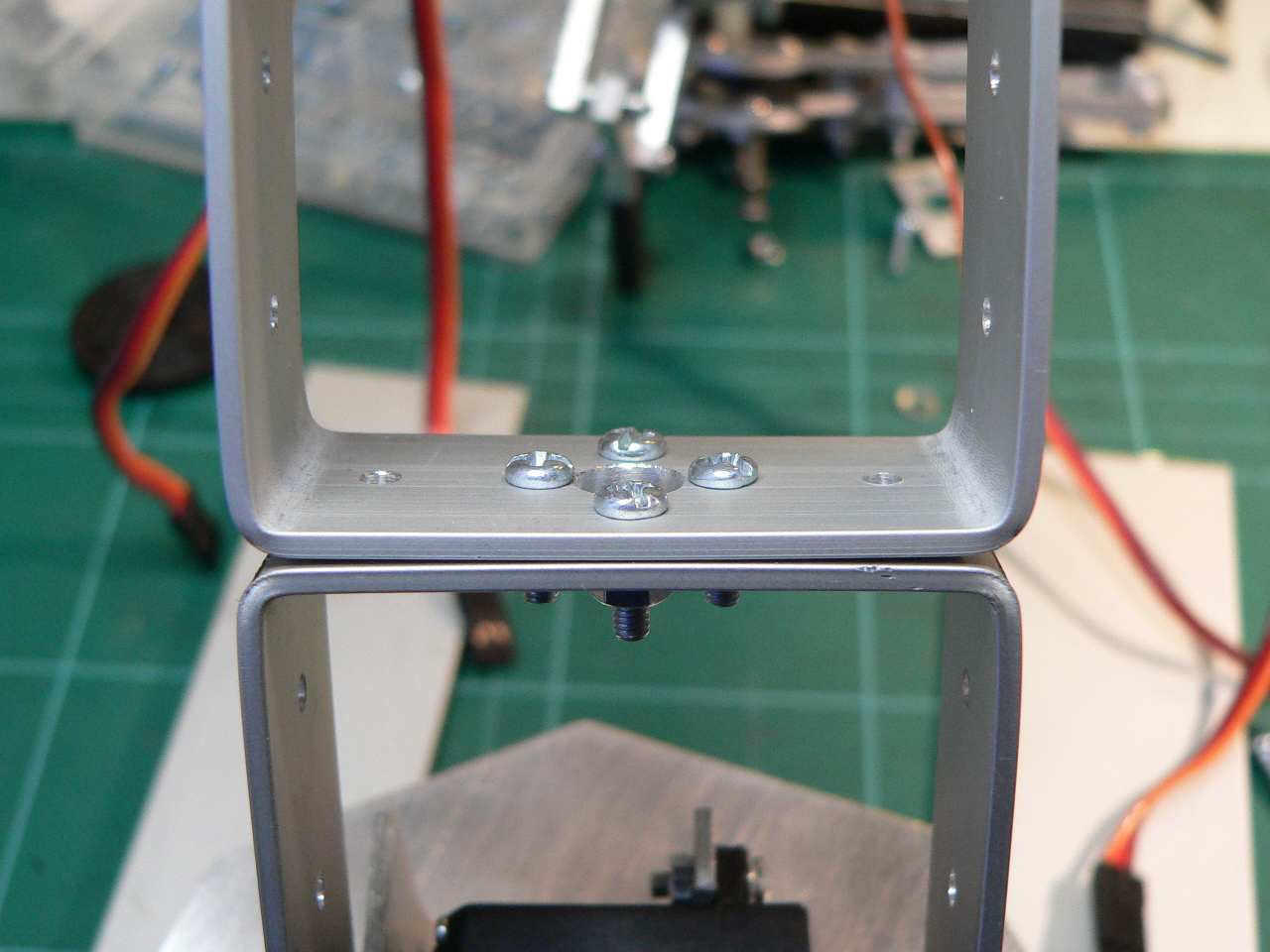
The top of the turntable is constructed similar to the base. Before mounting the top of the turntable to the base one of the servo mount brackets is attached to the top. You can see the finished turntable in the following picture. Note that the dual-servo bracket is raised slightly (on 4 M3 nuts) to give the robot arm clearance over the base when rotating the shoulder joint of the arm. You will need to drill out the base of the servo mount to allow the servo head screw to fit though so that you can hold the top of the turntable in place. You have to make sure that the hight of the turntable is correct for the servo used. You can raise the rollers by simply using washers underneath them.
Completed turntable
The following image shows the construction of the dual-servo bracket and mounts. The bracket consists of the dual-servo bracket with 2 servo-mount brackets bolted in place. Note that the front bracket has the back removed to allow the C bracket to be mounted to the rear servo before the front servo is mounted:
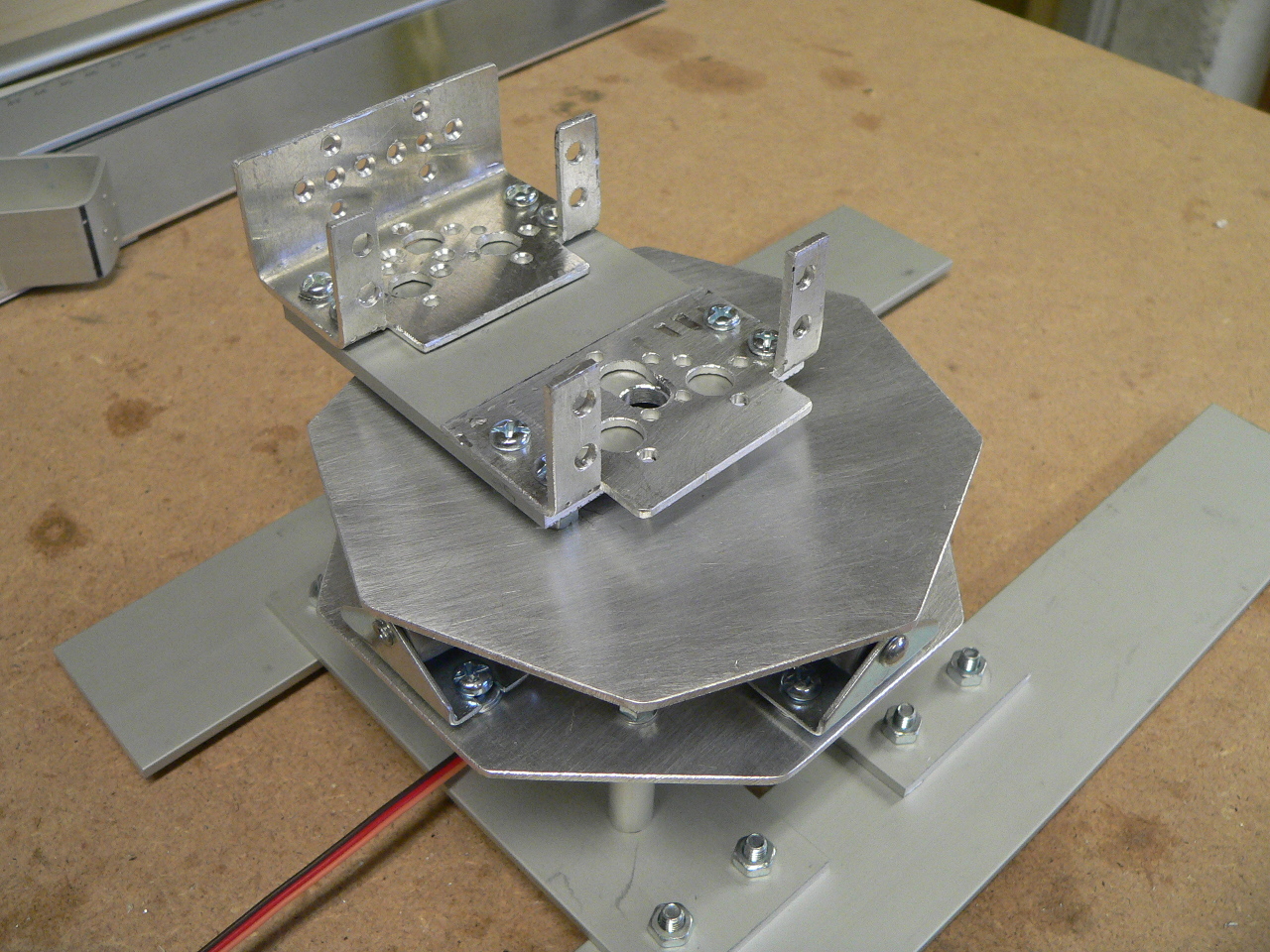
The dual-servo bracket mounted on the turntable
Assembling the robot arm
To begin assembling the arm mechanism start by bolting all the servos in place using M3 screws and nuts. As the arm requires a lot of torque to deal with the weight of the arm I used metal gear high-torque servos. The lower 5 servos (turntable, shoulder (x2) elbow and wrist) are SAVÖX SC-0252MG servos which produce 10.5kg/cm of torque at 6 Volts. The wrist-rotate servo is a Fubata S3003 standard servos which produce about 3.5kg/cm. All of the servos (except the wrist rotate) are metal-gear and dual-metal bearing to ensure that they are physically strong since the arm will place a lot of pressure on them.
Once mounted in the servo brackets the servos are then connected to the C brackets. On one side the servo head is mounted using the cross shaped servo head provided with the servo. These are cut to size and then screwed/bolted in place. On the other side of the bracket a flanged bearing is fitted to the 8mm hole which is then bolted through the bracket using an M3 screw and a nylon nut to prevent the rotation from unscrewing the nut (note that the flange of the bearing is on the outside of the C bracket). If the M3 screw is a little long you can use 2-3 M3 washers on the outside of the bracket to make sure it does not dig into the back of the servo.
The bearings have an inner diameter of 4mm, and outer diameter of 8mm and are 3mm thick. The bearings are flanged meaning that they have a small metal lip on one side which prevents them from being pushed through the bracket. This type of bearing is quite common in remote control car models and can be purchased either from a model shop or from sites such as Ebay. There are 4 bearings in all, 3 in the arm and one in the end-effector (see below).
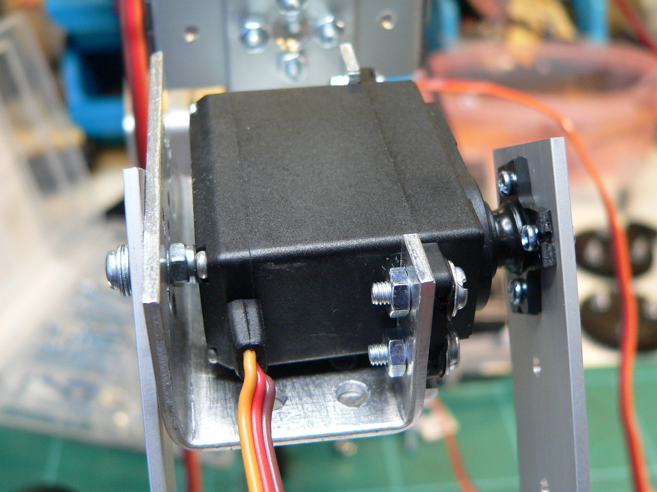
Mounted servo
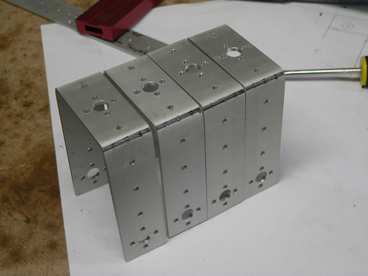
Once you have mounted the servo brackets to the C brackets it is a simple case of bolting together C brackets (as shown in the picture below) and the smaller L brackets to form the arm itself. The L brackets fit under the servo brackets and are secured using four M3 screws and nuts.
Two C brackets bolted together
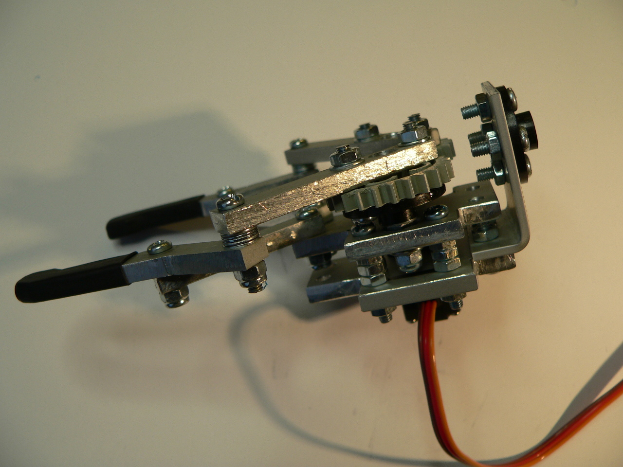
Building the end-effector
The end-effector design is based around two counter rotating gears which use levers to make the grippers open and close laterally rather than using a pincer-action. This allows the design to use relatively small parts but still achieve a open aperture of about 65mm to allow the arm to pick up quite wide objects. The biggest issue I found when making the effector was the gears. It is quite hard to find suitable gears which are easily sourced and not too large. In the end I decided to use 20mm Lego Technics gears which can be found easily in any toy store.
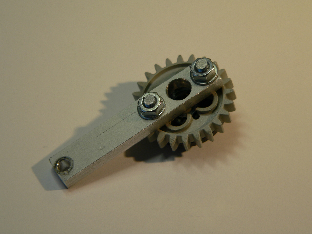
The first step is to drill two 3mm holes on either side of the Lego part. The gears I used had two handily placed mold markings which I dot-punched (very lightly!) and then drilled.
Once the part is drilled you will need to file down either side of the gear to make it flush with the outer hub of the gear. To do this simply rub the gear up and down on a flat-file (I found this was easier as gripping the gear in a vice is likely to damage the teeth as the Lego plastic is quite soft). Once the part is filed flat you can then use some small side cutters to remove the inner hub of the part. This has to be removed to allow the gear to be mounted to the end-effector in a later step).
Next, to mount the Lego gear to the servo and the second gear mount, you will need to drill two servo heads to fit the Lego parts. These are later bolted to the Lego part as you assemble the end-effector.
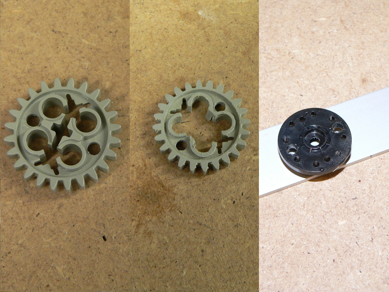
Drilled Lego gears
To build the end-effector you will need to print out the CAD template for the parts and cut the parts from aluminium. For the parts I used a 60mm x 1000mm x 4mm aluminium bar and cut the pieces using a combination of mitre-saw, jigsaw and a file to shape the pieces. Once the pieces are cut print out the CAD template and sticky-tape them to the parts (in the same way as making the brackets). The parts are then dot-punched and drilled. Note that, when cutting the smaller parts, having everything perfectly square is not terribly important; as long as you dot-punch and drill according to the CAD diagrams the holes will be the right distance apart and the mechanism will work.
Start by cutting the servo mounting bracket. For the servo I have used a DGServo S05NF which is small and light, but still metal geared and high-torque. The servo is attached to the bracket using 2 M3 screws and nuts:
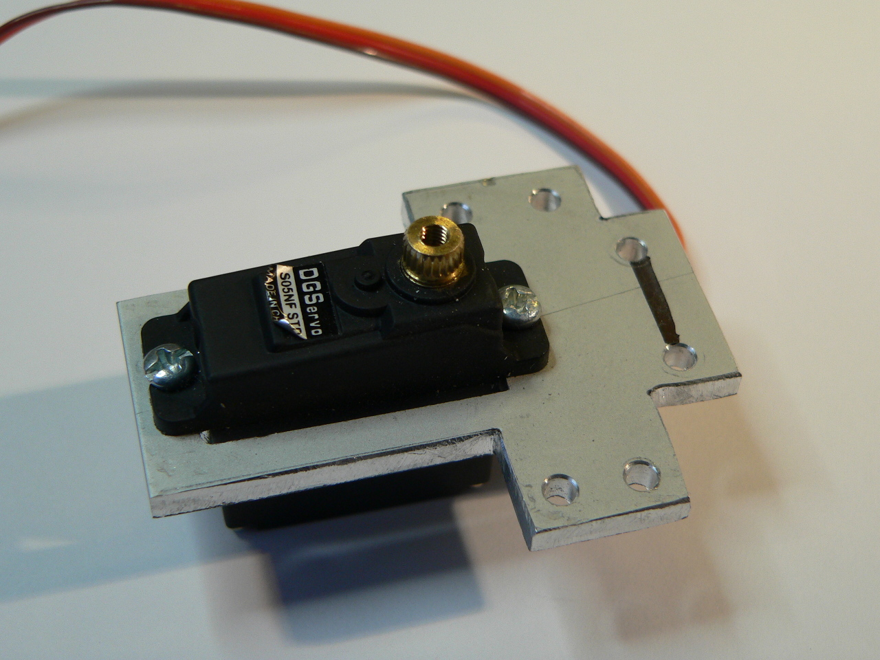
End-effector servo mount
Next cut the upper bracket. This bracket should have a flanged bearing pushed through the lower-side and two M3 screws. Each screw requires 3 nuts which act as spacers to rise the bracket from the servo mount:
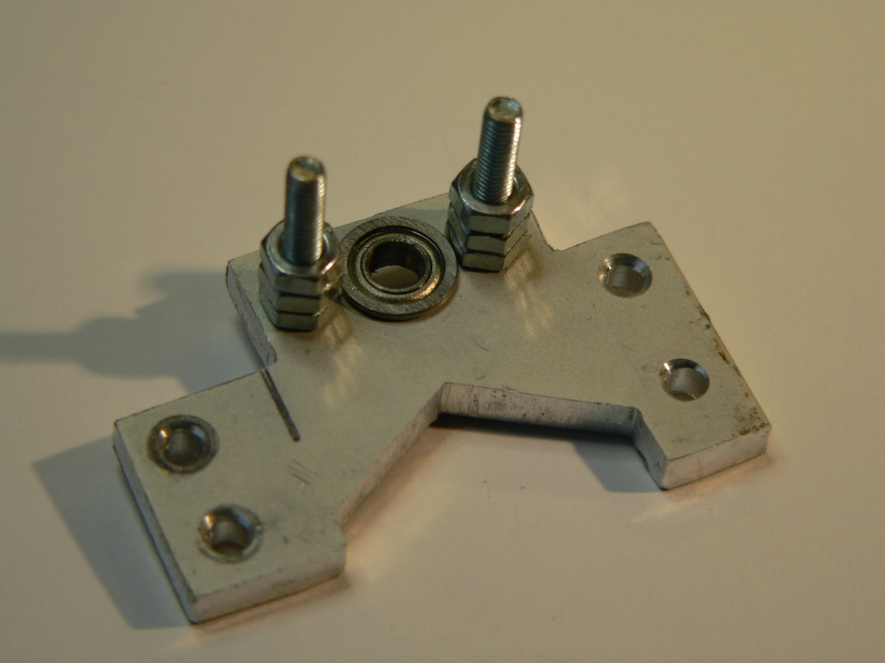
End-effector upper bracket
Now assemble the servo head. This consists of the Lego gear, one of the servo heads drilled earlier and a long lever part:
End-effector servo head
Next up is the other gear and lever. This part is similar to the servo gear however it has a long M3 screw bolted though to act as the pivot. To stop this slipping around in the bearing (the bearing has an inner diameter of 4mm and the M3 screw is 3mm) there is a small slip placed over the screw 3mm long. I made the slip out of some parts which came with one of the servos, however any 4mm slip will do:
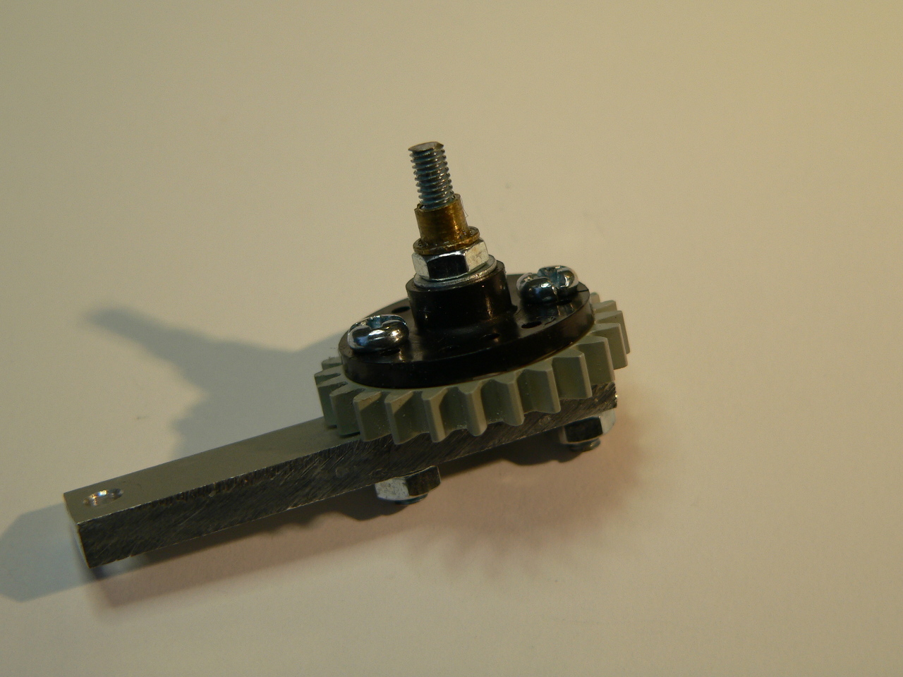
End-effector pivot gear
Now attach the pivot gear to the upper bracket using a nylon nut then attach the upper bracket to the servo mount using a further 2 M3 nuts:
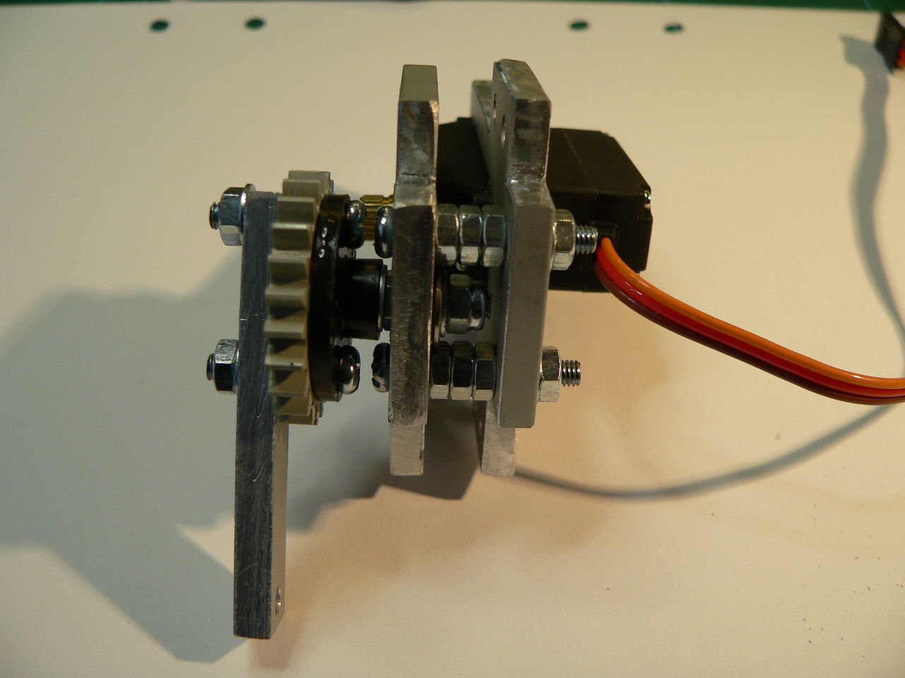
End-effector bracket assembly
Now assemble the two short levers, the servo gear and the gripping arms as shown in the following picture. Note that I have added two heat-shrink tubes to the gripping arms to increase the grip a little, these are simply cut and then heated into place. Use nylon nuts on the pivot points, tighten them up completely and then turn the screw back a quarter/half turn so that the parts can freely move over each other:
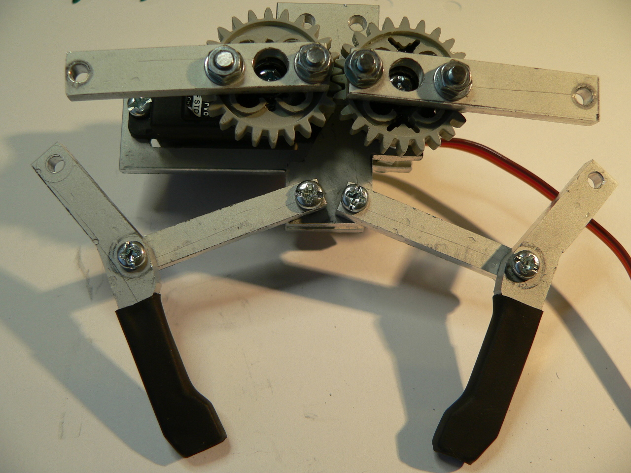
End-effector arm assembly
To finish the end-effector connect the upper levers to the lower levers. Since there is a gap in between the two you can use 5 or so washers to create a spacer (see the picture below). Once this is complete attach the short L-bracket to the back of the assembly:
Finished end-effector
Now you can attach the end-effector to the arm. Don’t forget to screw it in place to the wrist-rotate servo. The bracket is raised just enough so you can get a screw driver into the servo head.
Electronics
To keep the electronics as simple as possible to build I designed the control circuit based on an Arduino Leonardo (i.e. as an Uno R3 compatible shield). The Leonard board has an ATmega32U4 AVR microcontroller with built-in USB. This allows you to build a fully USB capable device without the hassle of soldering surface-mount components.
Since I wanted to supply 6Vs to the servos (to get the maximum torque) the custom ‘shield’ simply supplies Vin to the servos. The LDO regulator on the Leonardo ensures that the rest of the circuitry gets a steady 5Vs. The issue with hobby servos (especially high torque servos) is that, under load, the current consumption can be pretty high. Most tests performed on the web conclude that the peak draw is around 400mA per servo. Allowing for a little head-room (i.e. 500mA per servo) and the fact we have 6 servos, the power supply needs to be rated at over 3 Amps in order to do the job. I sourced a regulated 6-15V PSU from a local electronics store which can supply 5 Amps at 6 Volts, more than enough for the job. This supply is directly connected to the Leonardo’s power connector. It’s a good idea to pick a PSU with both overload and short protection, as this will help save your electronics if (when) you make a mistake.
Since the servos are directly connected to the Vin on the Leonardo you should not use a PSU which is rated above 6 Volts. Doing so will permanently damage your servos!
To make the shield as generic as possible I placed 7 servo output connectors on the board (one for each PWM output on the Leonardo). This means that you could use the shield design for any project requiring 1 to 7 servos. In addition I added a single LED for indicating status and a JTAG header. The JTAG header allows for more flexible programming and debugging if you have a JTAG programmer (such as the AVR Dragon).
Here is the schematic for the servo control shield:
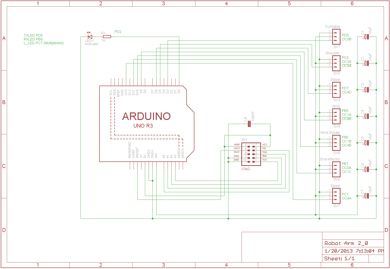
Robot Arm Leonardo shield schematic
The design is very simple so, if you cannot make your own PCBs, you can easily construct it using one of the Arduino prototyping shields available on the web. The following picture shows the underside of the PCB before it was drilled and populated with components:
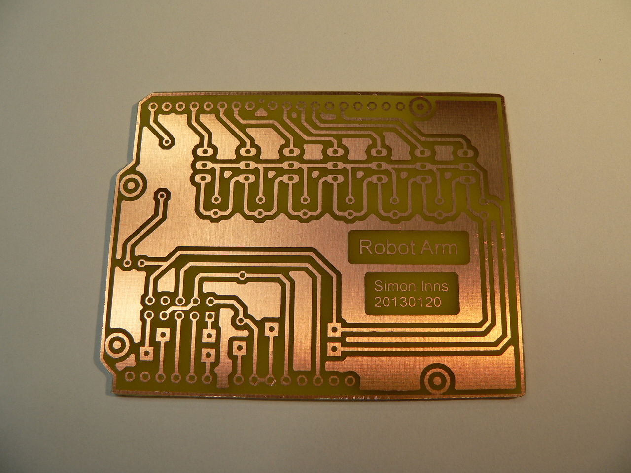
The servo shield PCB
Since servos can be very noisy on the power-rails I included a 10uF capacitor in-line with the power output to each servo to help deal with the peaking of the servos when starting up. There is also a 100nF capacitor in-line with the JTAG header to assist decoupling of the power-rails.
The EagleCAD schematic and board design is available for download below. Here is a picture of the completed shield connected to 7 test servos during software development:
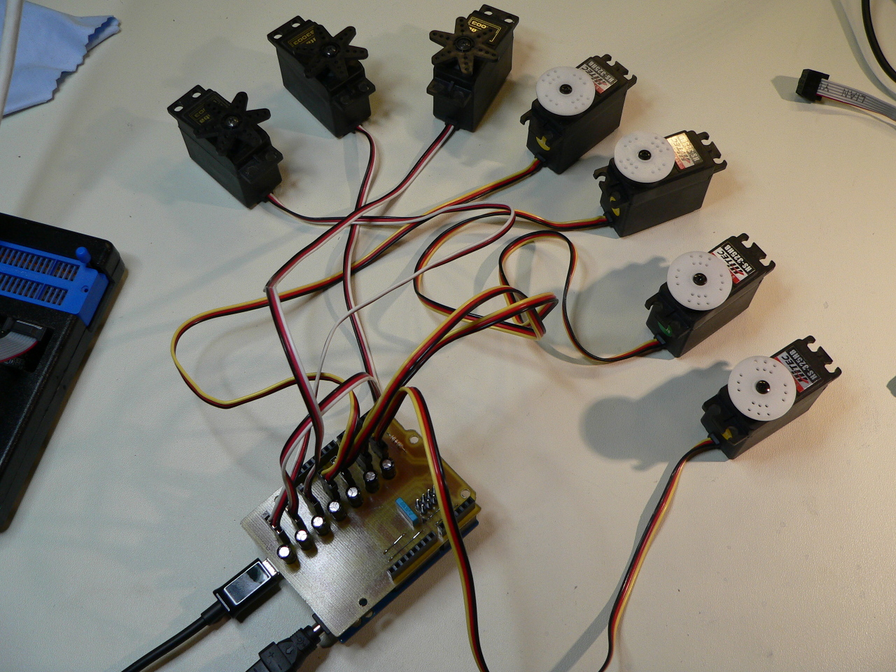
The servo control shield under test
Software
This project is still work in progress. The software design will be added shortly.
Conclusions
This article is part of an ongoing project to build a complete robot arm. Still to come is the software which I will be publishing shortly. So far I have tested the mechanics of the robot arm using a standard R/C radio control system to verify that everything moves correctly and that the servos can handle the load of the arm. The shoulder servo seems to be strained when the arm is extended flat out from the shoulder, but further testing is needed to see if a bigger servo is necessary.
Update 2013-01-21: I’ve finally got the fully servo control running enough to really test the arm and the shoulder servo cannot lift the arm from a flat-out 90 degree angle. This means I need to change the turntable design to either add another servo to the shoulder or replace it with a bigger servo. I will post an update shortly. The servo firmware is now running with rotational speed control; it’s just the servo rotation ramp-up and ramp-down which still needs to be implemented.
Update 2013-01-24: The turntable has been redesigned for simple dual-servo mount and I have replaced all the TowerPro servos (which performed really badly) with Savöx servos which work much better. Now the modified arm can lift even fully extended from angle straight out from the turntable. I have also updated the pictures and included the CAD for the new bracket.
Files for download
The following files are a zip containing the original libreCAD files for the robot arm and a PDF copy for the impatient:
LibreCAD drawings for the robot arm:
Robot_Arm_libreCAD_drawings_1_1
PDF file of the libreCAD drawings for the robot arm:
Robot Arm shield Eagle CAD files:
Hi,
I wondering if there is any updates on the software/electronics sections of this project. The hardware has been relatively simple to prepare, but I want to make sure I use the correct servos and Arduino components. I will have to buy my own Arduino prototyping shield — as I do not have the means of making one away from school (WashU in St. Louis).
I am on break in SLC, UT trying to complete this project with my 84-yr old grandfather. He really enjoys working with hardware — he used to weld fuel tanks on the Project Mercury rockets back in the day — and has taken to this project with more enthusiasm than I have seen in years.
If possible, can I get a compact list of all electronic/software components used?
I want to make sure I am getting the right equipment before I purchase anything.
He has already begun constructing the hardware and is getting very close to completing all the pieces from PDFs you have provided, so the sooner I can get electronics/software components in progress, the better! Coding in Arduino is likely all he will need me for, but I leave town in 12 days so I need to get electronics soon if we are to complete the project.
Regardless, this was a great post!!! His response to working on it with me has been nothing short of blissful. I thank you for that.
If you download the eagle CAD files you can produce a bill-of-materials directly (there is an option in Eagle to do this). As for the servos, any standard servo with the right torque will do, they just need to be the standard size (rather than micro, or over-sized).
I’m afraid I never quite got round to the software, but there are a number of servo driving libraries available for the Arduino and, since it’s just a collection of standard servos (and extension cables), they should all work perfectly for you.
As a note, there are also a number of ready-made servo control boards available; you might find it easier just to grab one of those.