Secure USB Time-Stamp for Data-Logging
Contents
This project implements a USB device which provides a real-time clock for the purpose of time-stamping events in an non-networked embedded computer environment. For embedded applications where a periodic time-stamp is required (such as entry-system logs, configuration audit logs, etc.) it is necessary to have a fairly accurate real-time clock (better than that typically provided by a PC’s motherboard) to generate time-stamps in logging and audit trails. Furthermore, it is preferable to have a method of confirming that the log/audit files have not been tampered with in anyway. The secure USB time-stamp device solves many of these issues in a very small form factor using minimal components.
The device logs the time at which the clock was last updated and (if requested by the USB host) the time when it last served a time-stamp. This allows the host application to examine it’s own logs and compare them to the time values stored by the device (to detect when logs have been altered). The device stores the last time setting and the last logged time-stamp in the PIC’s non-volatile EEPROM memory which can hold the data for up to 40 years without battery backup.
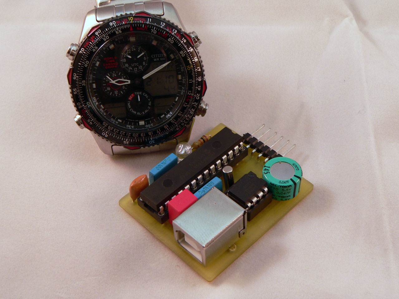
SUTS board
Hardware
The SUTS device is powered by a PIC18F2550 microcontroller which provides an on-board USB interface as well as the required SPI serial interface to the DS1302 real-time clock chip. To prevent loss of time setting when powered off or disconnected the DS1302 is backed up by a 0.047F super-capacitor. A super-capacitor was chosen (rather than a lithium cell) since it is harder to remove (preventing a casual or deliberate reset of the time), charges very fast (less than 5 minutes from empty to fully-charged) and is capable of powering the RTC for around 90 hours without losing time. Furthermore, the super-cap has a virtually unlimited lifespan and does not suffer from the restrictions placed on lithium devices (since it’s chemical make-up is more environmentally friendly).
Timing for the DS1302 is provided by a 32.768Khz clock quartz oscillator (which must have a load capacitance of 6pF in order to keep accurate time).
The PIC18F2550 requires an external oscillator in order to use the USB transceiver module, so a 20Mhz resonator with built in capacitors is used (since the DS1302 is responsible for time-keeping the PIC does not need a more expensive crystal oscillator). An ICSP header is also included on the board, but can be omitted if the PIC is programmed and code-protected to prevent alteration of the firmware. The device is powered by the USB host connection and requires no external power-supply unit.
Here is the circuit schematic for the SUTS board:
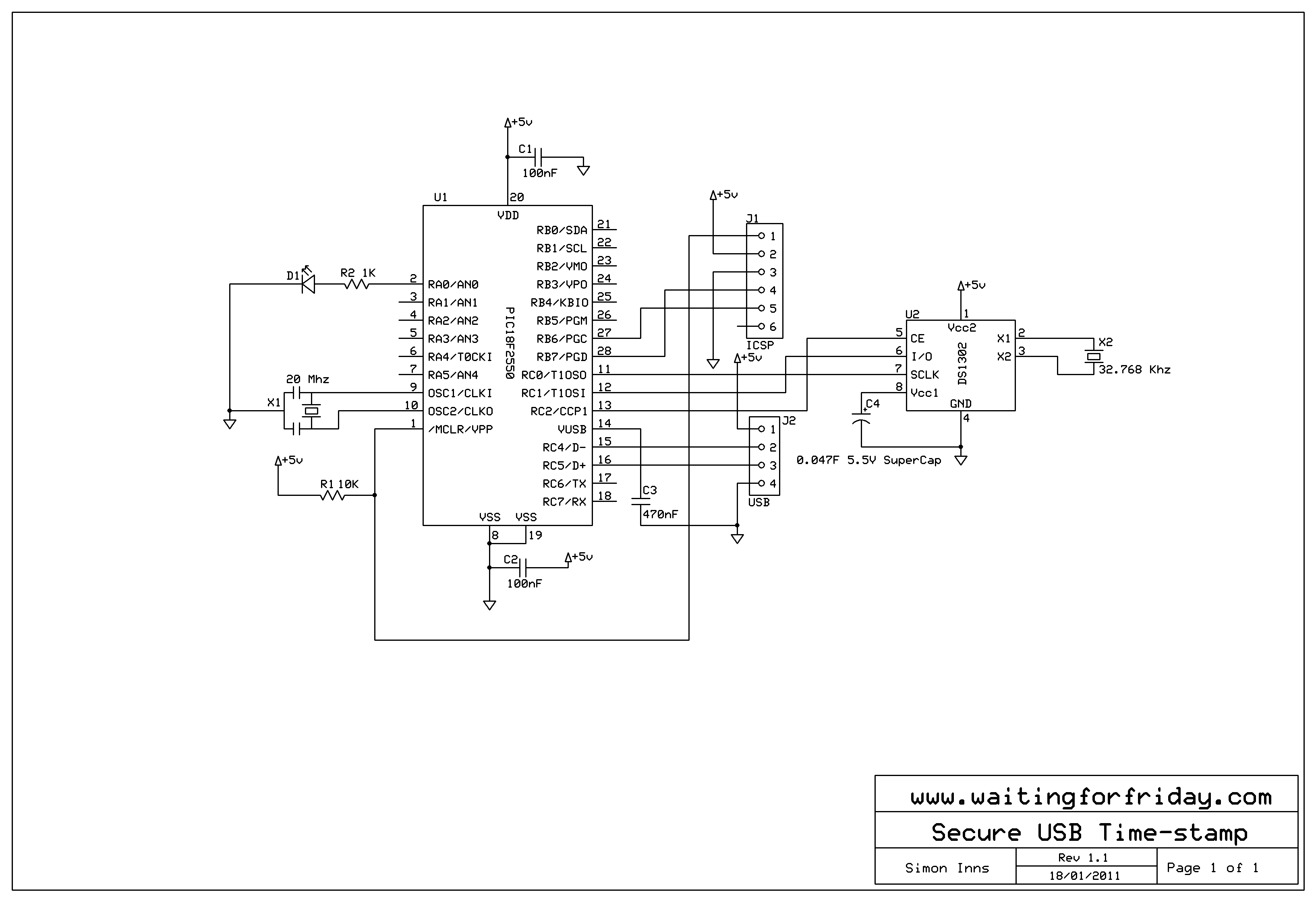
Secure USB time-stamp SCH
The circuit board design is a single-layer PCB using only through-hole components to make it as easy as possible to duplicate. No wire links or vias are required. Here is a picture of the PCB artwork which is included in the downloads section below:
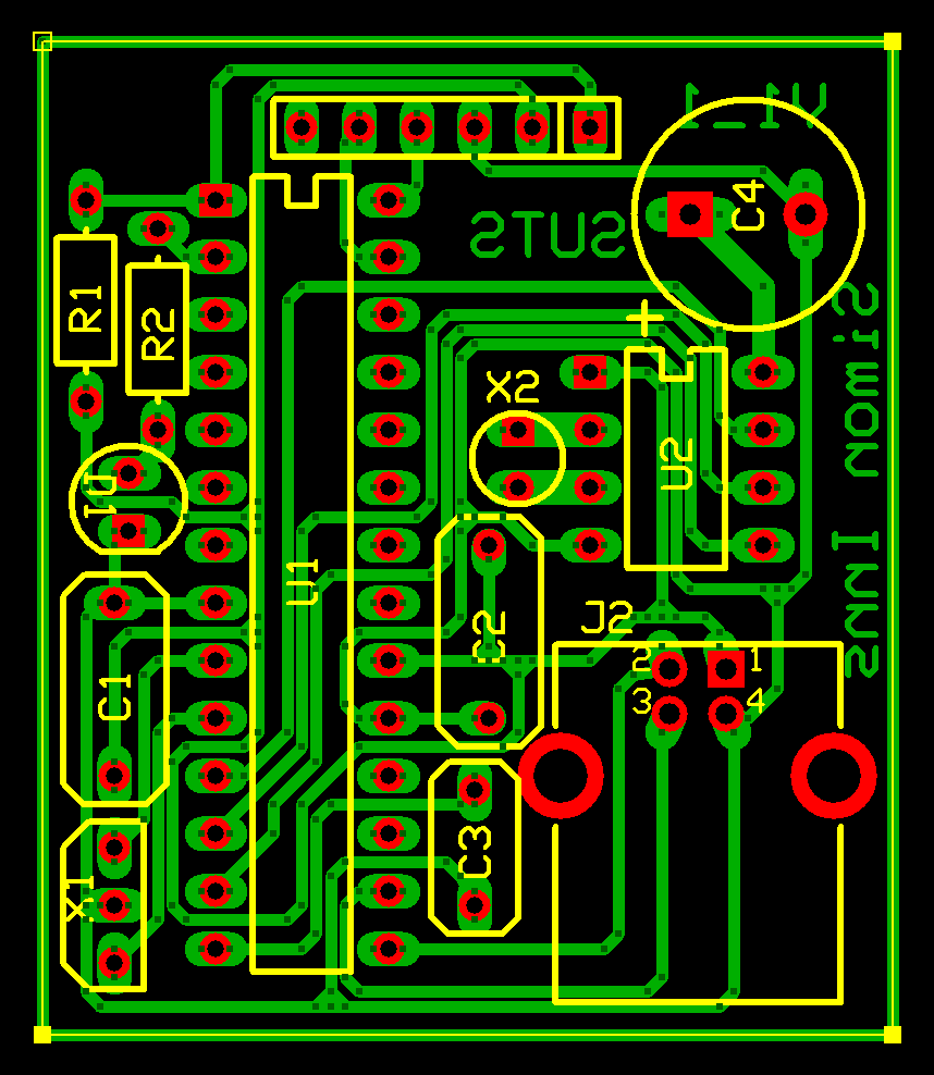
SUTS PCB Artwork
Firmware
The firmware is completely written in Hi-Tech C and is based on my Open Source Framework for USB Generic HID devices based on the PIC18F and Windows. It is available for download in the downloads section below.
The firmware provides the following commands via the USB Generic HID protocol:
0x80 – Set the RTC time
The host passes the date and time to the device and the device sends the information to the DS1302, also the information is stored in the EEPROM for later retrieval (as the last date-time at which the clock was set)
0x81 – Read the RTC (not logged)
Once the device receives the command the current date-time of the DS1302 is passed back to the host including a ‘clock status’ flag which is zero if the DS1302 has not been set (or has lost its time information due to depleted backup power) or one if the device is running normally. The clock status flag lets the host know if the received data is valid or if it needs to set the clock (the clock status is also show by the LED on the device which is only lit after the clock is set). This command does not cause the device to log the date-time to EEPROM so can be used for regular fast-polling reads of the time.
0x82 – Read the RTC (logged)
This command is the same as 0x81 however it also causes the PIC to store the read date-time in EEPROM. The EEPROM is rated for approximately 1,000,000 write cycles with a retention span of >40 years. This means that at 500 time-stamp readings per day the device would last approximately 5.5 years. For applications where a greater number of time-stamps per day are required (or if the device life-span must be higher) it is recommended that the host uses a 0x81 command several times before periodically using a 0x82 command to maximum life-span (of course this will require the host application to be more intelligent when verifying the last stored time-stamp).
0x83 – Read the last time logged by the device
This command returns the date-time of the last logged time-stamp to the host. The host must insure that this is valid data (the PIC will return all values at 255 by default if the EEPROM has not been written to previously).
0x84 – Read the last clock set time from the device
This command returns the last clock set time which was stored when the last 0x80 command was issued to update/set the RTC.
Windows host test application
A simple Windows host test application demonstrating the functions of the board and allowing testing is provided in the downloads section below. The USB communication is provided by my Open Source Framework for USB Generic HID devices based on the PIC18F and Windows. Here is a screen-shot of the application:
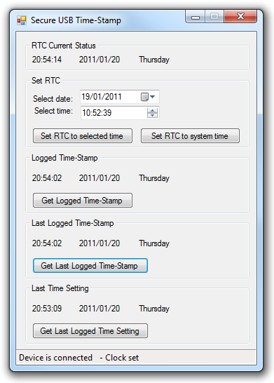
SUTS Windows application
The ‘RTC current status’ group box displays the current status of the device by polling the device using command 0x81 5 times a second.
The ‘Set RTC’ group box allows you to select a date and time which can be used to set the device’s RTC (by issuing a 0x80 command), or you can simply click on ‘set RTC to system time’ to copy the host’s current system time to the RTC.
The ‘Logged Time-stamp’ group box allows the user to issue a logged read (command 0x81). The result of the logged time-stamp is shown in the group-box.
The ‘Last Logged Time-Stamp’ allows the user to retrieve the stored time-stamp date-time value using command 0x83.
The ‘Last Logged Time setting’ allows the user to retrieve the date-time value last used to set the RTC using command 0x84.
The status bar at the bottom of the window shows if the USB device is detected and also the status of the RTC (set or unset).
Conclusions
The Secure USB Time-Stamp device allows host applications to provide accurate time-stamping for non-networked environments even in industrial grade metal enclosures where radio-time devices would not function. Furthermore the device provides the host with a method of simple verification of stored logs and audit files.
Files for download
The PCB artwork and schematics in expressSCH and expressPCB format (these are freely available programs):
Secure_USB_Time-Stamp_Schematics
The PIC18F2550 firmware source code (for HiTech C18):
Secure_USB_Time-Stamp_V1_1_PIC_firmware
The Windows test application written in Visual Studio 2010 C#: