Stylophone Studio 5
Contents
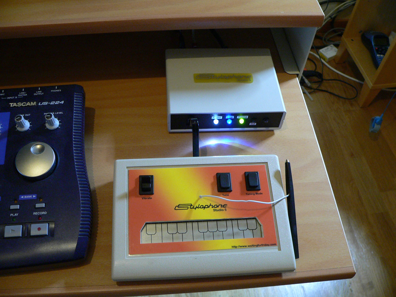
The Stylophone Studio 5 is a project to recreate the original 1968 Dubreq Stylophone which sounds and reacts just like the original (and even contains a replica of the original circuitry) however it also fully supports both MIDI in and MIDI out over USB and can be controlled by studio software such as Cubase.
There have been plenty of projects on the web allowing MIDI out from modified Stylophones (which is fairly easy to do since it only requires an ADC on the original keyboard output), however providing MIDI in to the instrument is far more complicated to achieve (which is why versions 1 to 4 never made the grade!). Since the original Stylophone is completely analogue the control circuitry must be carefully designed so as not to interfere with the sound of the instrument. Furthermore the original is 9 volts which means it cannot be directly controlled by a microcontroller.
The Stylophone Studio 5 design overcomes these issues and even provides features not possible on the original such as pitch-bend control and automatic tuning. The original 1968 Stylophone was available in three different tunings: bass, standard and treble. Each of these tunings was implemented by changing capacitor values on the circuit. The Stylophone Studio 5 supports all three models using an automatic circuit reconfiguration. The tuning, vibrato and overall tone output is all controllable via MIDI.
Although I do own an original 1968 Stylophone (from which all of the reverse engineering was performed) and it is possible to alter the original for both MIDI in and out (using the same techniques detailed here) I decided it was better to build from scratch as I didn’t want to damage my original in any way. At all stages the audio output from both the Stylophone Studio 5 and the original were compared on an oscilloscope to ensure as much likeness as possible in the sounds.
YouTube Demonstration Video
Hardware
The hardware can be split into 4 distinct sections: the microcontroller, the Stylophone tone generator, the frequency counter and the Stylophone control panel and keyboard. Each one of these parts is described in detail below.
The Microcontroller
The microcontroller is an Atmel AVR ATmega32U4 which was chosen for several reasons. It has in built USB and can support MIDI using the LUFA USB stack and it has a very high frequency PWM generation which is required as part of the DAC which controls the primary oscillator. The microcontroller also provides ADCs which are used to read the keyboard to detect keypresses. The microcontoller also connects to the CD4066 analogue switch ICs which are used to provide control between the 5V microcontroller and the 9V Stylophone oscillator.
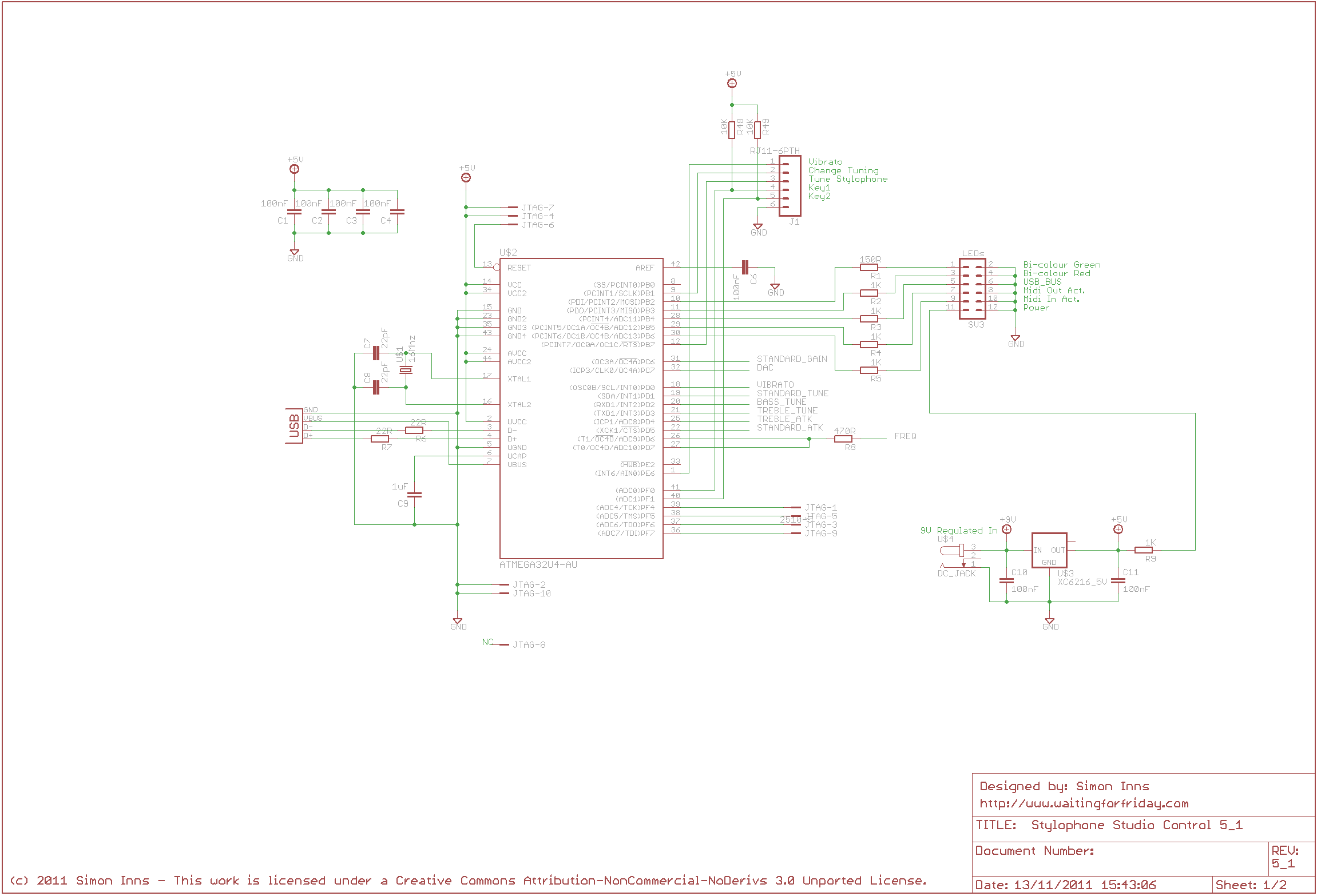
The overall schematic for the microcontroller is shown below:
The Stylophone Tone Generator
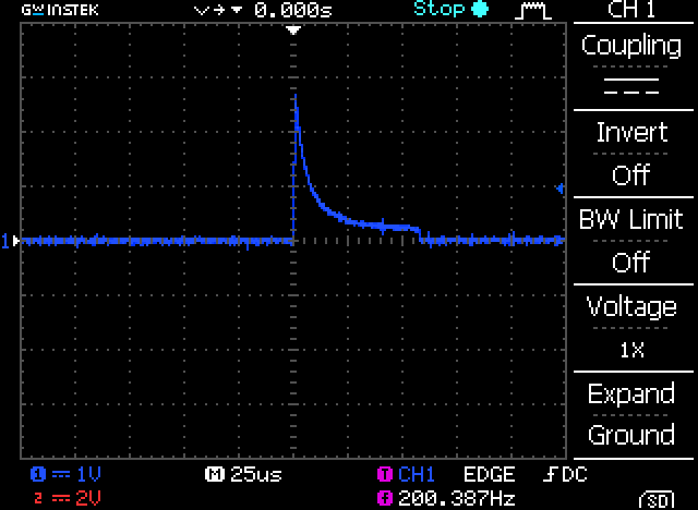
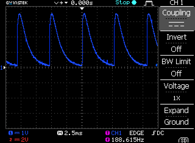
The tone generator is a combination of two oscillators. The primary oscillator is a current controlled PUT (Programmable Uni-Junction Transistor) relaxation oscillator which is responsible for generating the overall tone of the instrument. A secondary low-frequency phase-shift oscillator provides the vibrato (vibrato is the relative slow wavering of a sound around the notes centre pitch). The sound produced by the Stylophone is quite ‘brass’ like due to the output shape of the PUT, the following DSO trace shows the leading-edge of the typical waveform from the cathode of the PUT:
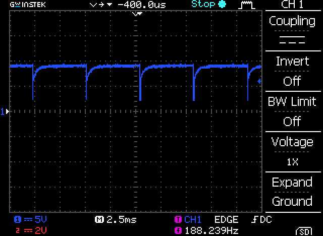
The final stage of the generator is a simple one transistor inverting amplifier which (in the original model) powered the inbuilt speaker. Since the Stylophone Studio 5 does not have an inbuilt speaker it is replaced with an equivalent resistor. The output from the amplifier is then passed through a resistor to the line-out socket. Since the bass Stylophone’s output is considerably louder than the standard and treble Stylophones an analogue mixer channel is included to attenuate the bass output when required to ensure a more uniform output volume no-matter the tuning setting. The following DSO trace shows the output of the Stylophone Studio from the inverting amplifier:
Since the original Stylophone used a resistor network to control the pitch of the Stylophone, the PUT relaxation oscillator is current controlled. So in the design we pass 9Vs through an analogue switch. The analogue switch is controlled with a high-frequency PWM signal from the microcontroller which has 10-bit accuracy (meaning that 0% duty-cycle is 0 and 100% duty-cycle is 1023). Note that the high-frequency (around 94 Khz) is required so that the series resistor and capacitors (already present in the original design) can act as an RC filter to the PWM signal which smooths out the PWM and ensures no artefacts of the signal are present in the final sound.
If we place a 10000 ohm (10K) resistor in series with the output from the multiplexor (R1) and have the PWM at 100% duty (on all the time), the current output from the circuit can be predicted using ohms law which states:
I = Vin / R1
So in this case I = 9 / 10000 = 0.0009
Since this is fixed we can only vary the voltage V using the PWM. With a voltage of 9V and a PWM duty-cycle of 50% the average voltage over time is 4.5V. This means that the effective resistance of the circuit is doubled (and therefore the current (I) is halved):
I = (Vin / 2) / R1
I = 4.5 / 10000
I = 0.00045
Using this we can simulate different resistance values by varying the PWM duty-cycle. For example using the formula above we can state that:
Vadj = (Vin / 100) * d
Where Vavg is the average voltage given for Vin and the current duty-cycle (d) in %.
Therefore, given a known value for R1 we can calculate the overall resistance (z) of the circuit using:
z = Vin / (((Vin / 100) * d) / R1)
Since Vin is cancelled out by this equation we can simplify it to:
z = (100 * R1) / d
Which means, if we know the value of R1 and the required overall resistance ‘z’ we can calculate the required duty-cycle by solving the equation above in terms of d:
d = (100 * R1) / z
For example, if we require a resistance of 20000 ohms (with R1 equal to 10000 ohms) we get:
d = (100 * 10000) / 20000
d = 1000000 / 20000
d = 50%
Note that the minimum resistance we can represent is fixed by the resistor on the multiplexer’s output pin. The maximum is dependent on the resolution of the PWM.
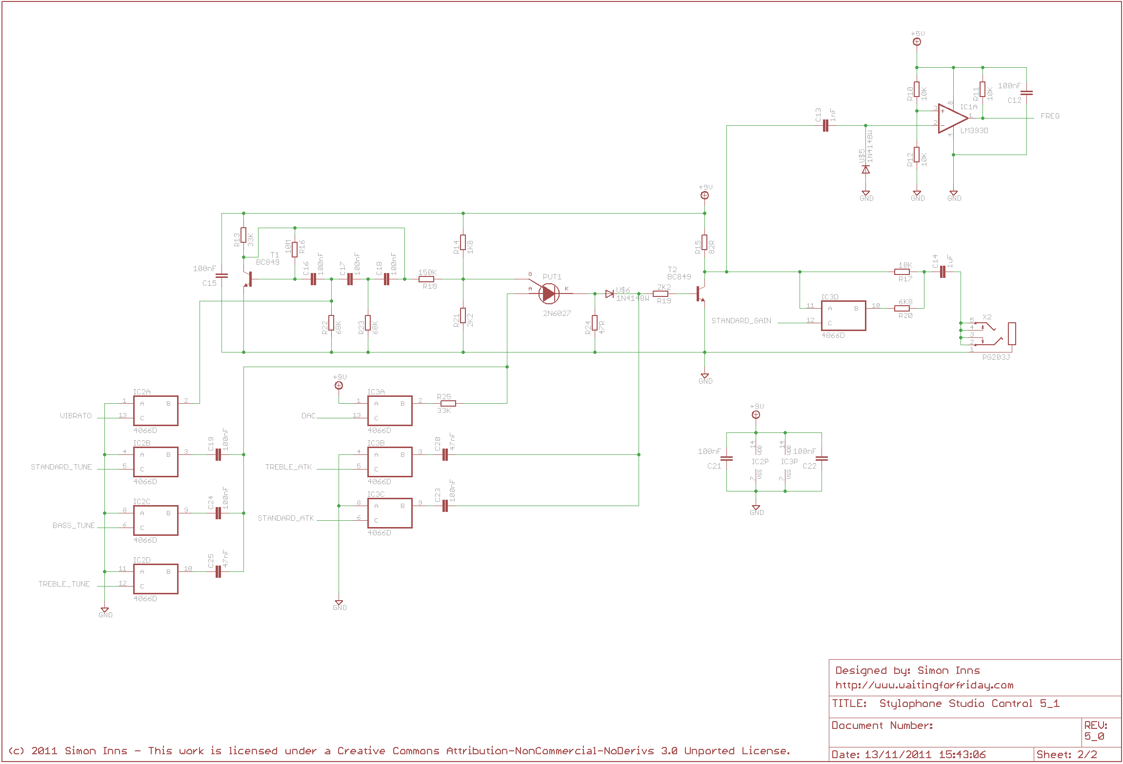
The overall schematic for the Stylophone tone generator is shown below:
The Frequency Counter
Since the oscillator is analogue the frequency produced by the oscillator for a given current is based on the dynamics of the PUT and the tolerance of the surrounding components, even using 1% tolerance resistors and good capacitors the output is still variable from circuit to circuit and (to make matters worse) is also effected by environmental conditions such as temperature. This means that the Stylophone Studio requires a frequency counter to allow it to automatically tune the Stylophone. The frequency counter uses a timer/counter on the microcontroller however, since the oscillator output is both AC and 9 volts it must be conditioned before being fed to the counter. The frequency counter uses a capacitor/diode combination to remove the negative part of the output signal and bias the signal from 0Vs as shown in the following DSO trace:
This is then fed into a comparator which converts the triangle-like wave output into a 5V peak square-wave which can drive the microcontroller’s timer input. Since the frequencies are relatively low (as they are audio signals) the microcontroller requires a relatively long sample to get an accurate reading (1 second). To ensure it only counts during the 1 second duration a second pin on the microcontroller is used to allow and deny the signal as required.
To speed up tuning further it is possible to predict the output frequency from the PUT oscillator for a known PWM duty-cycle however the maths is quite involved. To do this we need to return to my original Reverse Engineering the Stylophone project where I demonstrate how to calculate the possible output frequencies of the Stylophone based on the functioning of the PUT relaxation oscillator, the resistance to 9Vs and the value of the tuning capacitor.
The procedure is basically the same as the original Stylophone however in the Studio design the resistor values are fixed (there is no tuning potentiometer) so we calculate the value of η (eta) from the 1K8 and 2K2 voltage divider. Following the circuit diagram we can calculate eta as:
η = 2200 / (1800 + 2200) = 0.55
Once we have eta the formula for calculating the frequency is given as:
Frequency = 1 / ( resistance * capacitance * ln(1/(1- eta)))
Since eta is a constant we can calculate this first and fix it in the formula:
x = ln(1/(1-eta)) = 0.798507696 = 0.8 (rounded up)
So now our formula becomes:
f = 1/(r * c * 0.8)
For the standard tuning the value of c is 100 nano-farads. This should be represented in farads giving a value of 0.0000001 farads.
Since we need the required resistance we have to solve the equation in terms of r, so firstly we simplify the formula above:
f = 5 / (4 * c * r)
And then solve it in terms of r:
r = 5 / (4 * c * f)
To make things easier in the code we can produce and simplify three formulas (one for each tuning mode) where we set c as a constant.
For bass tuning (where C is 200nF) the formula becomes:
Bass_resistance = 6250000 / f
For standard tuning (where C is 100nF) the formula becomes:
Standard_resistance = 12500000 / f
For treble tuning (where C is 47nF) the formula becomes:
Treble_resistance = 26595745 / f
Now we go back to our original calculation that calculates the required duty-cycle based on the target resistance:
d = (1023 * R1) / z
Since (from the circuit diagram) we know that R1 is 33Kohms this gives:
d = 33759000 / z
and we know that to calculate z (for standard tuning) we can state that:
d = 33759000 / (12500000 / f)
So now if we insert the required frequency (f) we get the required duty-cycle (d) for standard tuning. Again we can simplify the formula one more time (to make the numbers smaller):
d_standard = 33759 * f / 12500
We can now do the same thing for both the bass and treble tuning modes to complete our set of formulas:
d_bass = 33759000 / (6250000 / f)
d_treble = 33759000 / (26595745 / f)
and simplified:
d_bass = 33759 * f / 6250
d_treble = 613800 * f / 483559
So, as a final example, if tuning is standard and the required frequency is 220Hz we would require a DAC value of 594.1584 to produce the correct tone:
D_standard = 33759 * 220 / 12500 = 594.1584 from a 10-bit duty-cycle
This calculation is used in the firmware to pick a sensible starting point for tuning so as to save time during the process.
Control panel and keyboard
The control panel and keyboard consist of 3 control switches (for the vibrato, tuning mode and to activate automatic tuning) and the Stylophone’s keyboard. In honour of the original the keyboard is also based on a resistor network, however in this case there are two resistor networks which feed the input to two of the ATmega’s ADC inputs.
In order to calculate the correct resistor values for the networks I used a simple Ohm’s law calculation which allowed me to calculate what values would be needed to ensure that each note has a non-overlapping voltage range which can be easily read by the ADC. The calculation is based on resistors with a 5% tolerance (however in the final build I used 1% tolerance resistors):
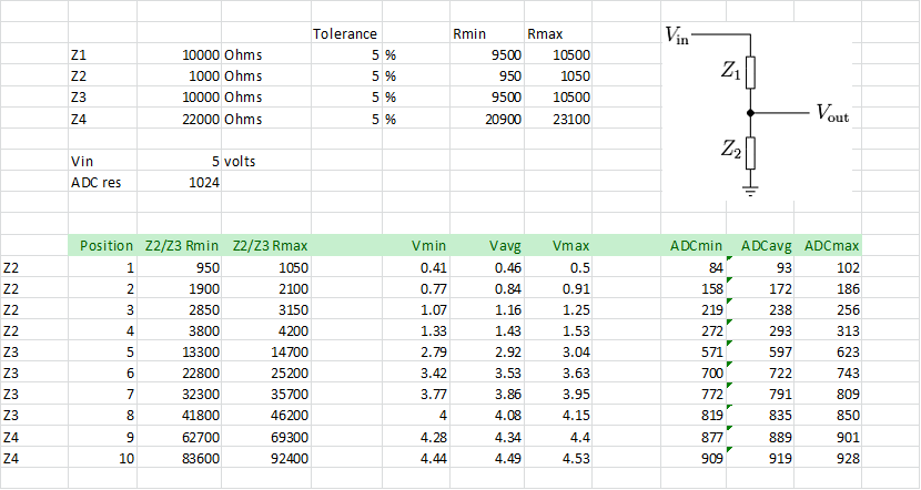
As can be seen in the table, by using increasing sizes of resistors you can get separated values for each of the two sets of 10 keys, the resulting circuit schematic is shown in the following diagram:
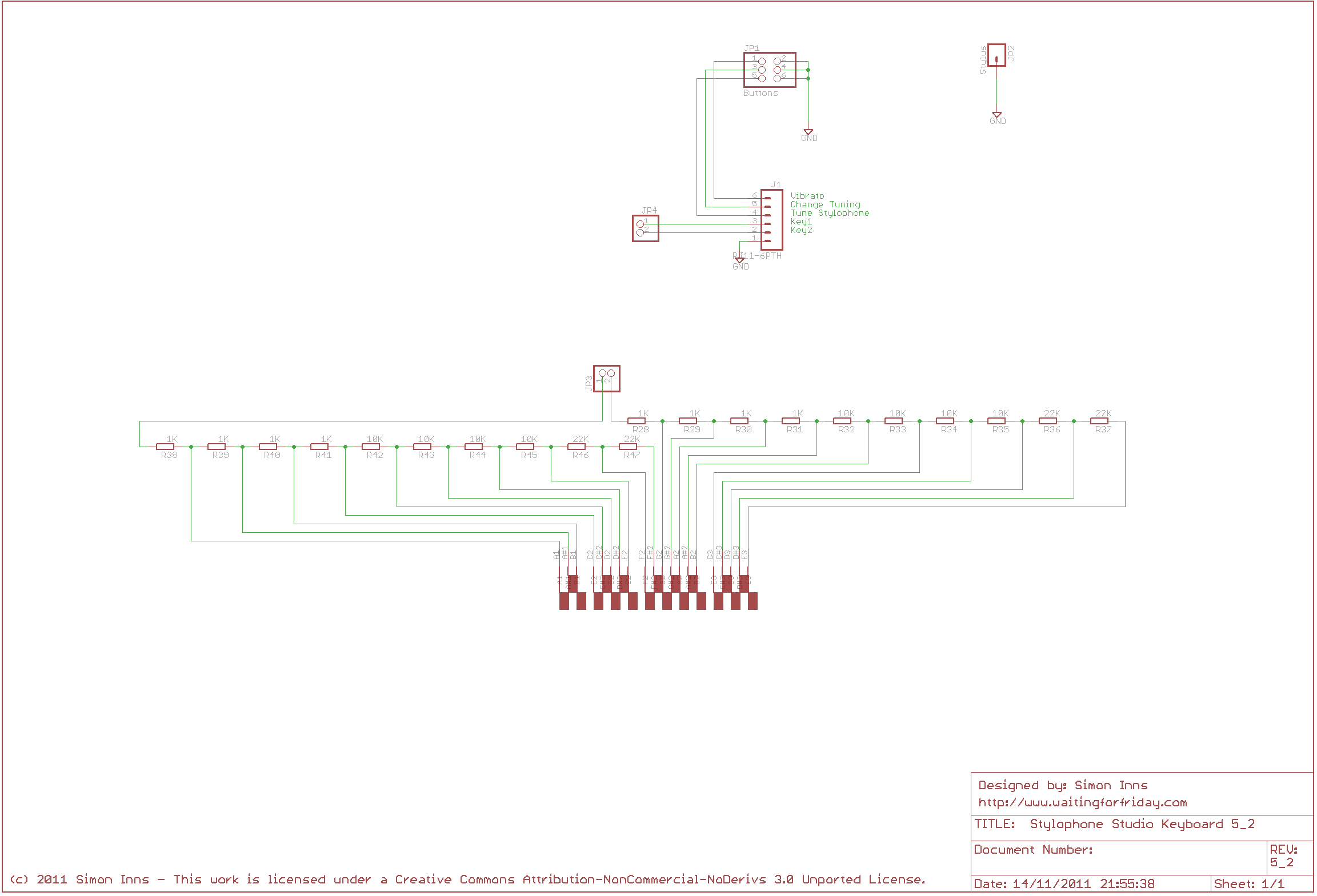
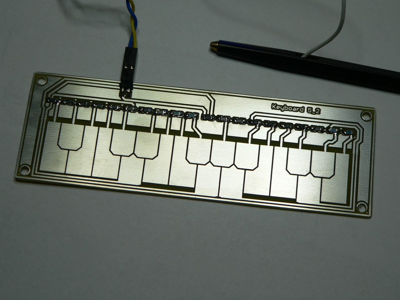
In the Eagle CAD file I created a custom part which is an exact representation of the original keyboard for the Stylophone to make producing a PCB much easier. The tin coating (which you can see in the pictures and video) was applied using Liquid Tin which makes the surface much more resistant to wear and scratches than a plain copper PCB. I also used much bigger switches to make it easier to play and control the instrument.
You can see the finished PCB complete with tin coating in the following picture:
Firmware
The firmware is based on the LUFA USB stack and provides both MIDI in and out via USB. For both MIDI in and out the firmware supports the following commands:
- Note on
- Note off
- Program change (sets the tuning, 0 = bass, 1= standard and 2 = treble)
- Pitch-bend (semi-tone range in both directions)
- Control Change (1 – Vibrato on/off)
The firmware code is fairly self explanatory and is heavily commented to aid reading and understanding. The only ‘confusing’ module is the note-stealing algorithm. Since the Stylophone is monophonic it requires an algorithm to deal with polyphonic events being passed via MIDI (more than one note on at a time). The note-stealing algorithm decides which note to play when more than one note is sent. It is basically a linked list which operates on a FIFO (First In First Out) basis, however it is a matter of taste and playing style when deciding how it should be implemented. I did it in the style that I felt most natural to me, you are, of course, welcome to dream up your own schemes.
The firmware is designed to operate with or without USB connectivity. If USB is connected then all events are sent as MIDI out commands to the host. If the USB is not connected the Stylophone operates exactly the same allowing it to be used with out a computer connected.
The firmware is provided as an AVR Studio 5 project and contains all the required source files for both the Stylophone and the underlying LUFA stack.
Cases
The Stylophone Studio sound module is mounted in a Velleman G738 enclosure (and the PCB is designed to fit over the mounting holes provided). The keyboard is mounted in a PacTec KEU-7LP enclosure.
The front panel for the keyboard was made by printing the required graphics onto glossy photo-paper (using an ink-jet printer). This was then laminated (using a normal office laminating machine) and then the holes for the keyboard and switches were cut. Once cut it was passed once again through the laminating machine before being glued in place on the front of the enclosure.
Files for download
This zip file contains both the AVR Studio 5 firmware project and the Eagle CAD board and schematic files for the project.