Valiant Turtle
Contents
The Valiant Turtle is a floor roving robot made by Valiant Technologies and was a popular education robot for teaching geometry and programming during the 1980s and 1990s. The robot was first sold in 1983 and was often used with the LOGO programming language.
I started writing this article in 2009 when I obtained my first Valiant Turtle, however the turtle was not repairable due to the stepper motors being destroyed. Now (in 2016 and two turtles later!) I finally have a restored and working robot. Since it was such a struggle to find the necessary information on the turtle, I have collected the results of my research here. I hope this will make your restoration project easier than mine (and a lot quicker!).
It is possible to connect the turtle using either serial or parallel connections from a microcomputer. Supported models (that I’m aware of) are the BBC Model B, RM Nimbus 186, Acorn Archimedes, Commodore 64, Apple IIe and a modern 9-pin serial connection to a PC.
Here is a video of my restored Valiant Turtle in action:
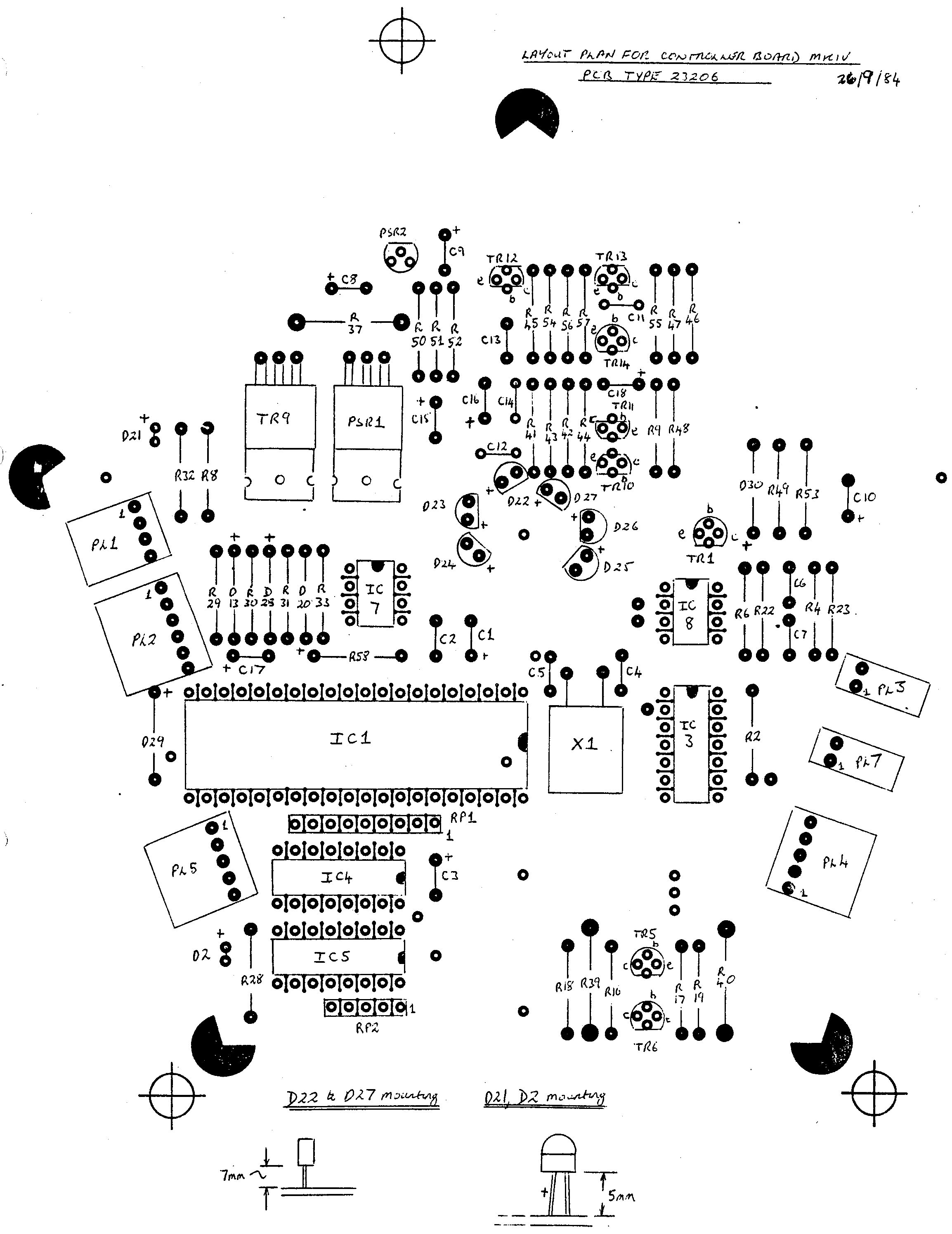
The Commander MKII control unit
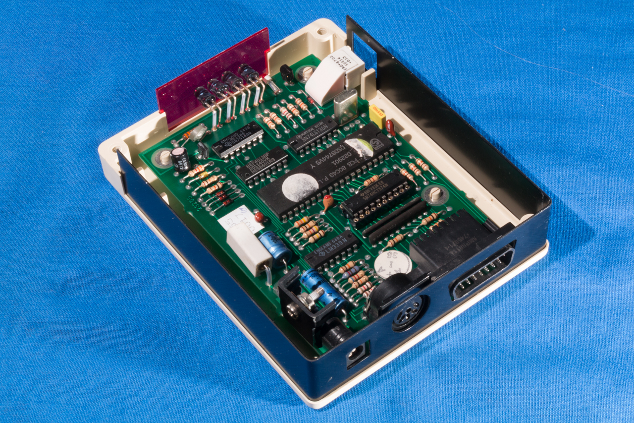
The control unit has 3 connectors; a 15 pin male D-sub parallel connector, a 5 pin female DIN serial connector and a 2 pin power supply socket. The Valiant Turtle service manual contains the following circuit schematic for the MKII version:
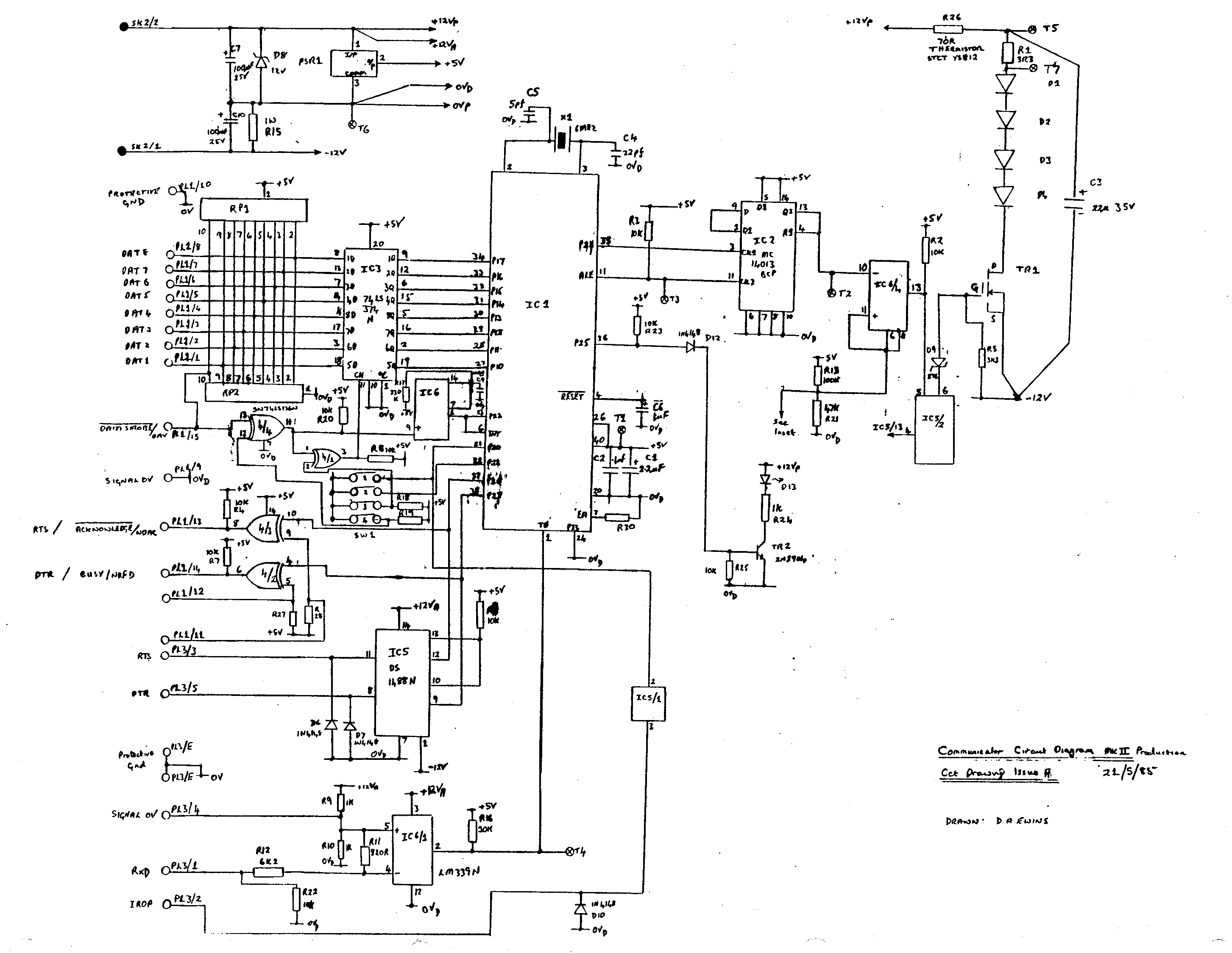
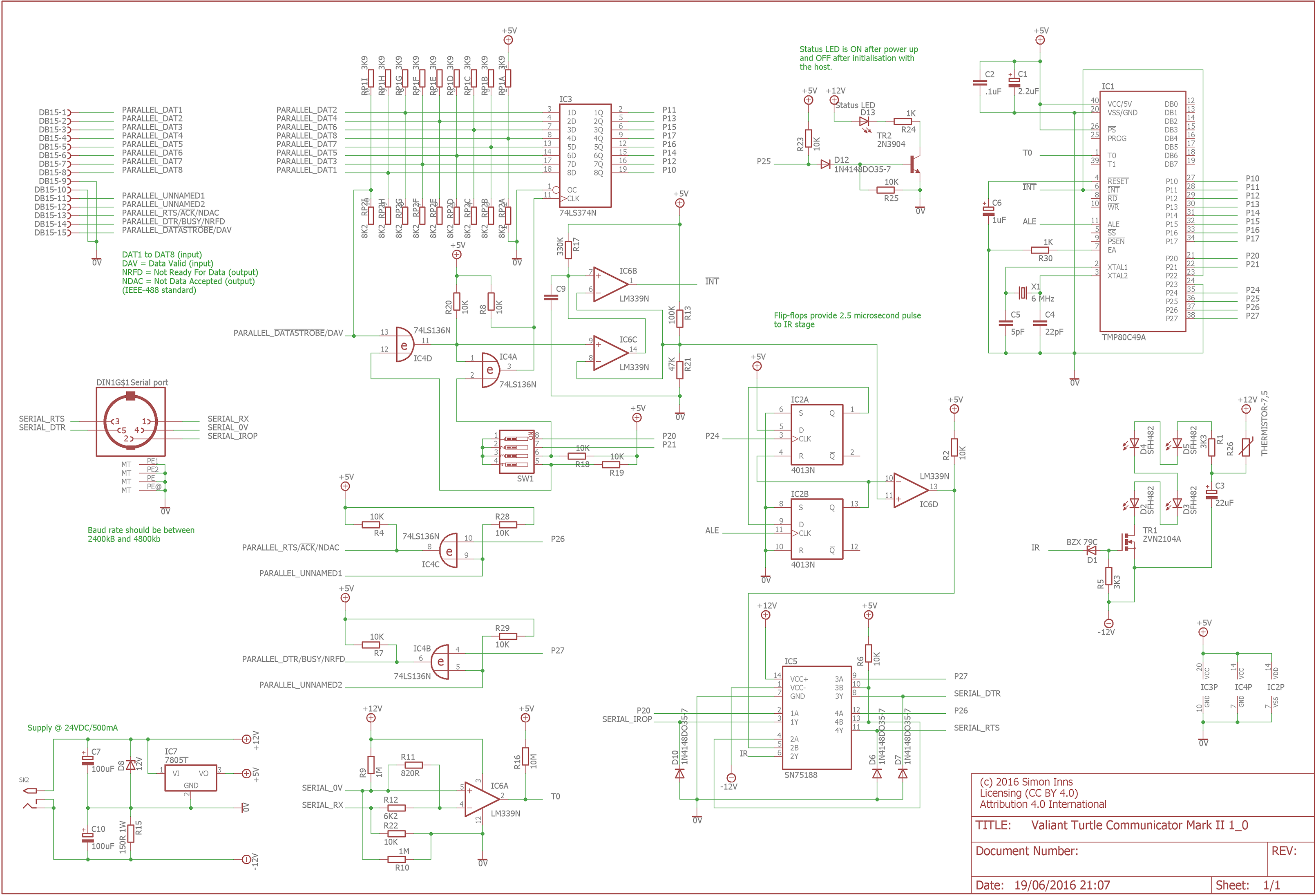
Since this diagram is low resolution and hard to read (also there are some component values missing) I have recreated the schematic in Eagle CAD including much more detail about the ports and notes about the operation of various parts of the circuit:
The service manual also provides a board layout diagram showing the placement of the various components shown in the schematic:

Power supply
The original power supply supplied with the turtle also doubles as a charger. The rating of the original PSU is 19V @ 500mA. Whilst this is good for charging the turtle, it’s not so good for the control box (which gets really hot). I would suggest that, if you have an original power supply, you only use it for charging and power the control box from 6-9Vs. My Turtle’s control box is powered from a 6V @ 500mA power supply.
The DC jack connecting the power supply to the control board should be centre-positive.
Serial cable
The serial connector for the BBC Micro requires that the the RTS and CTS lines are linked together. Since there were no diagrams available on the web, I have included a diagram of the required connections below:
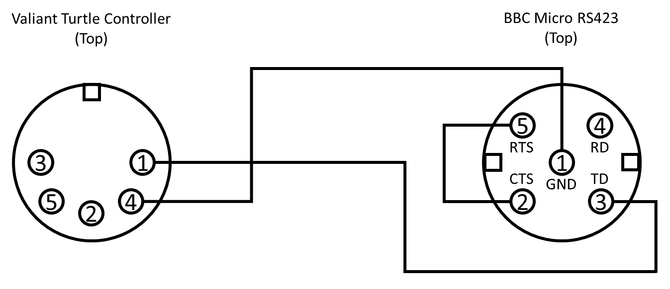
In order to use a serial connection the control unit needs to be configured for the Valiant Mover software on a serial interface. There are 4 switches on the side of the unit which should be set as: 1-ON, 2-ON, 3-OFF and 4-OFF. Furthermore the two switches on the base of the turtle should be set to OFF.
Whilst the cable shown above works perfectly with a BBC Micro there are other connections available from the controller board (I constructed the cable before performing a more detailed reverse-engineering of the controller circuitry). The Eagle CAD schematic of the controller gives a detailed view of the available serial port signals that may assist if you are attempting to connect the turtle to other types of computer.
Parallel cable
If you want to use the turtle with languages such as Acornsoft’s logo, the turtle must be controlled using a parallel cable (connected to the BBC Micro’s user port) rather than serial. Since there was no information about this available on the web, so I reverse-engineered the cable pinout from the control box circuitry. Here is the pin out (this has been tested successfully with Acornsoft Logo on the BBC):
BBC micro User Port to Valiant Turtle DB15:
- 01 (+5V) -> Not connected
- 02 (CB1) -> Pin 14 (DTR/BUSY)
- 03 (+5V) -> Not connected
- 04 (CB2) -> Pin 15 (!Data strobe)
- 05 (0V) -> Not connected
- 06 (PB0) -> Pin 1 (DAT1)
- 07 (0V) -> Not connected
- 08 (PB1) -> Pin 2 (DAT2)
- 09 (0V) -> Pin 9 (signal 0V)
- 10 (PB2) -> Pin 3 (DAT3)
- 11 (0V) -> Not connected
- 12 (PB3) -> Pin 4 (DAT4)
- 13 (0V) -> Not connected
- 14 (PB4) -> Pin 5 (DAT5)
- 15 (0V) -> Not connected
- 16 (PB5) -> Pin 6 (DAT6)
- 17 (0V) -> Not connected
- 18 (PB6) -> Pin 7 (DAT 7)
- 19 (0V) -> Not connected
- 20 (PB7) -> Pin 8 (DAT 8)
The control unit needs to be configured for the parallel interface. There are 4 switches on the side of the unit which should be set as: 1-OFF, 2-ON, 3-ON and 4-ON. Furthermore the two switches on the base of the turtle should be set to OFF.
DIP Switch Settings
There are three modes that can be selected using the communicators DIP switches:
- 1-ON, 2-ON, 3-OFF, 4-OFF – Serial port communication
- 1-OFF, 2-ON, 3-ON, 4-ON – One byte parallel communication (supports only 1 turtle with ID:0)
- 1-OFF, 2-OFF, 3-ON, 4-ON – Two byte parallel communication (supports up to 4 turtles)
Note that DIP switches 3 and 4 enable the (NOT) data-strobe line on the parallel interface. DIP switches 1 and 2 are read by the communicator’s processor directly.
In two byte parallel communication mode all commands are split into two bytes; the first byte identifies the turtle (to which the command is to be sent) and the second byte contains the command. Two-byte command mode is only supported over the parallel interface.
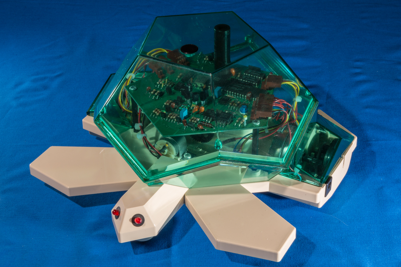
The Turtle
Main board
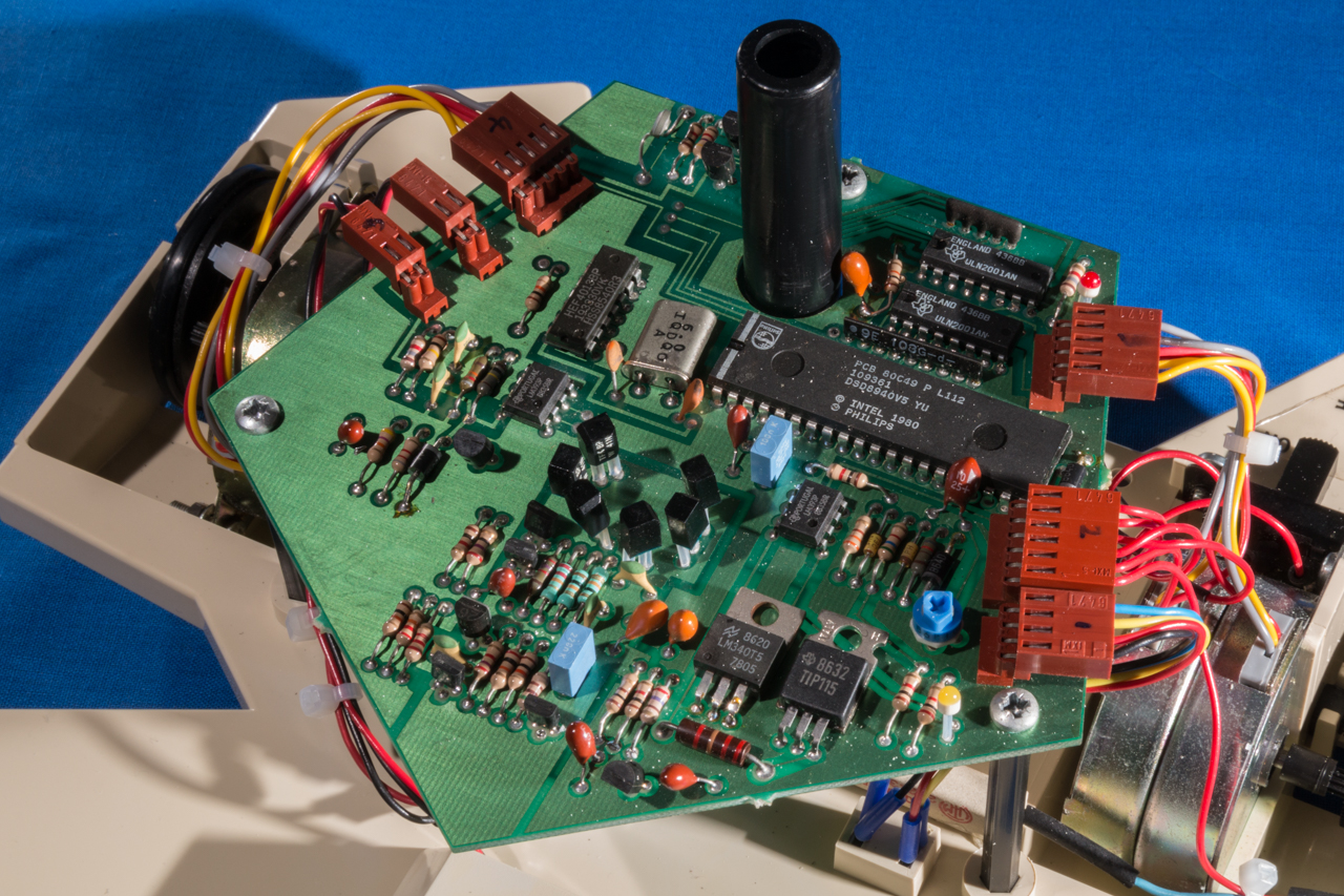
Similar in design to the to the control unit; the turtle’s main board is a microcontroller based board with IR receivers in the centre. When the turtle is switched to ‘on’ the red LED should light (and the turtle’s eyes), when switched to ‘charge’ the yellow LED should light.
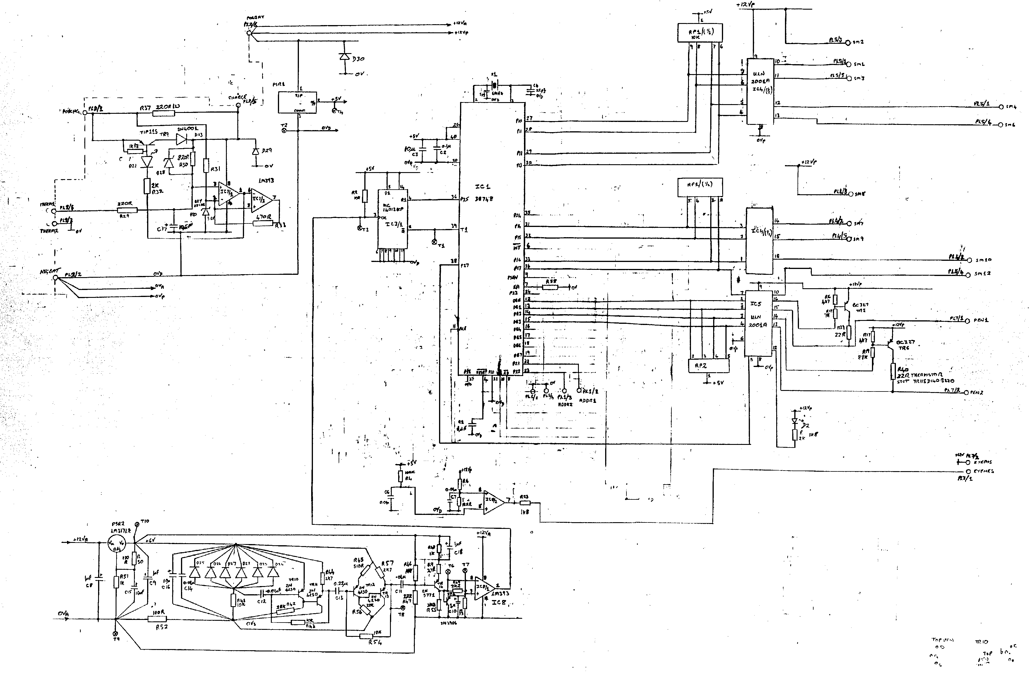
The service manual provides the following circuit diagram for the turtle’s main board:
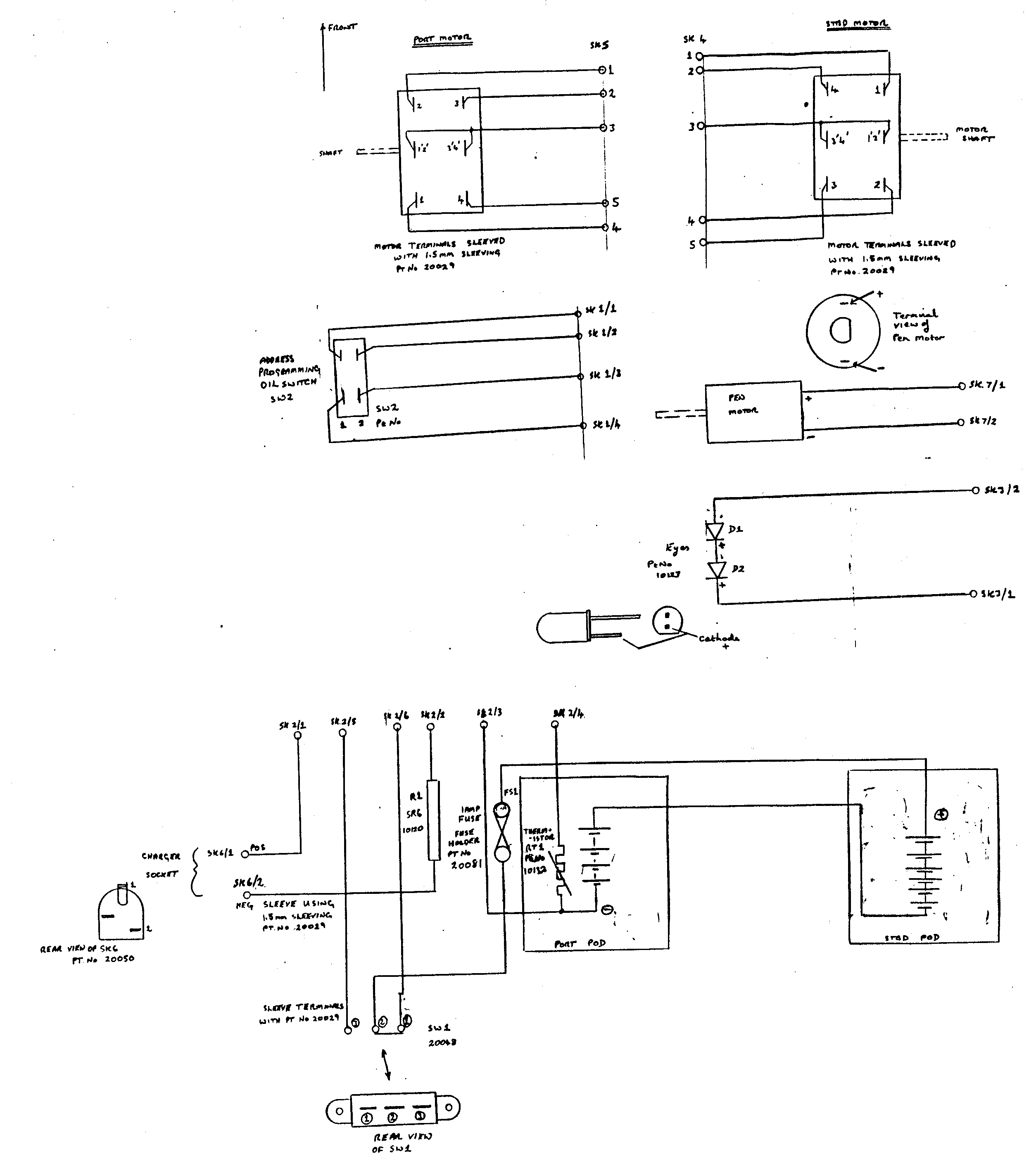
In addition the service manual also shows the schematic for the various external components such as the motors and batteries as shown in the following diagram:
The layout of the various components on the main board are shown in the following diagram (also from the service manual):
Batteries
If you have an old turtle like mine then the chances are the battery pack has been there a long time and is probably badly corroded. Luckily the corrosion does not affect the plastic, although you will have to remove the battery connectors and replace them with new ones or clean them completely. To remove the batteries remove the covers on the top and the bottom of the machine (you will have to take the main board off first, make sure you note which connector goes where as the LED and pen motor both have the same connectors).
To replace the batteries I used some NiMH 2400mAh AA cell rechargeable batteries (you need 10 in all); if the springs in the battery compartment are completely missing you can buy the ones ready-made with soldering tags. Simply connect them up like the old batteries, replace the battery connectors and reassemble.
The case should be properly cleaned and any battery ‘goo’ removed. You can use a 50/50 mix of vinegar and water to do this (the ‘goo’ is alkaline, so vinegar is good for neutralizing it).
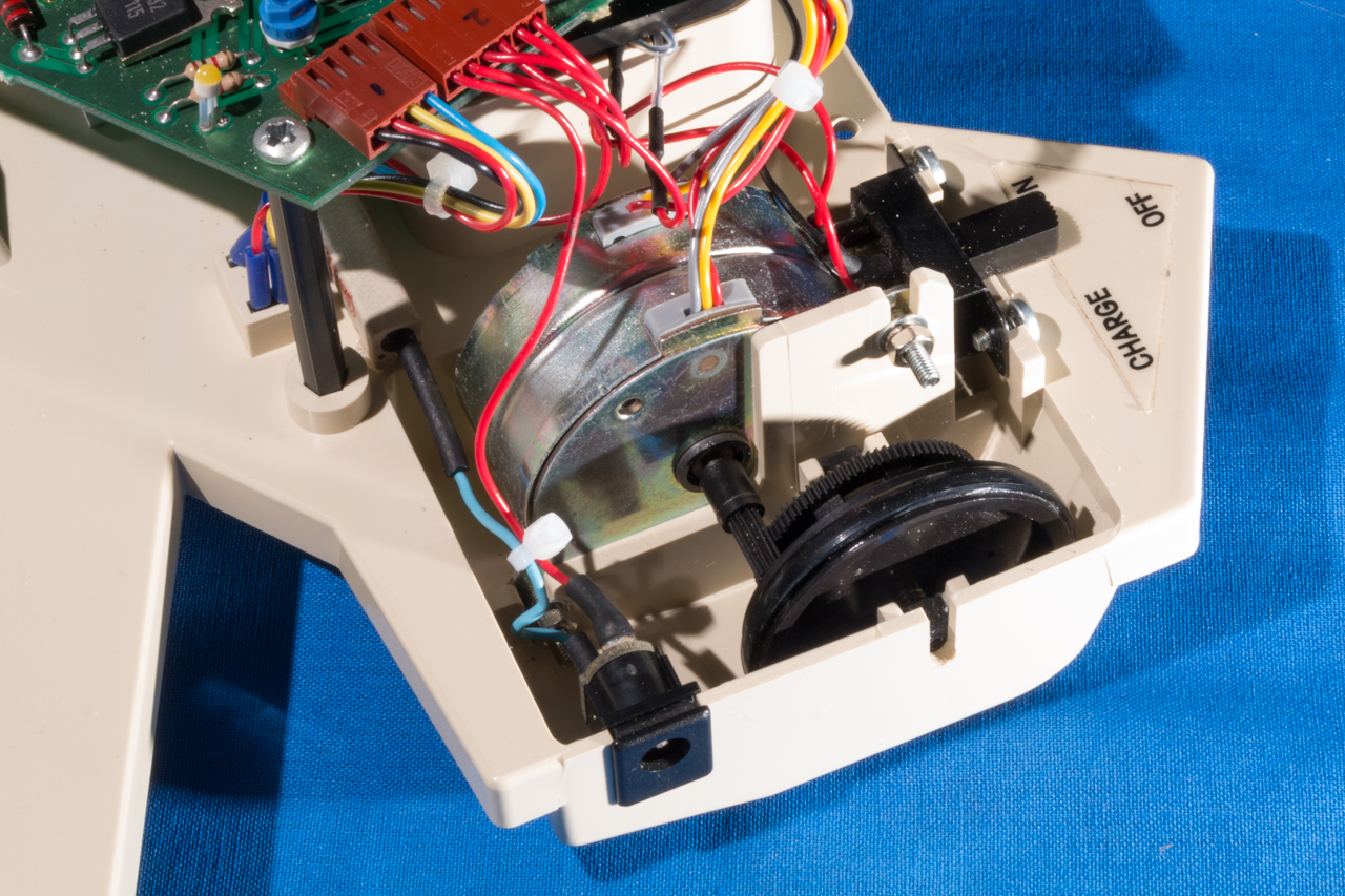
Stepper Motors and wheels
The stepper motors are manufactured by Sterling Instruments Limited and have a phase resistance of 60 Ohms and a step angle of 7 degrees and 30 minutes. The stepper motor and wheel assembly can be seen in the following picture:
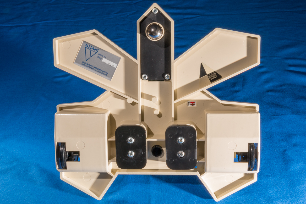
Underside
The underside of the turtle contains the battery compartment covers and a small ball bearing which acts as the front-wheel of the turtle. There are also two DIP switches that are used to set the ID of the turtle (Acornsoft Logo can use up to 4 turtles at once, but each one must have a unique ID):
DIP Switch Settings
There are four IDs that can be selected using the turtle’s DIP switches:
- 1-OFF, 2-OFF – ID:0
- 1-ON, 2-OFF – ID:1
- 1-OFF, 2-ON – ID:2
- 1-ON, 2-ON – ID:3
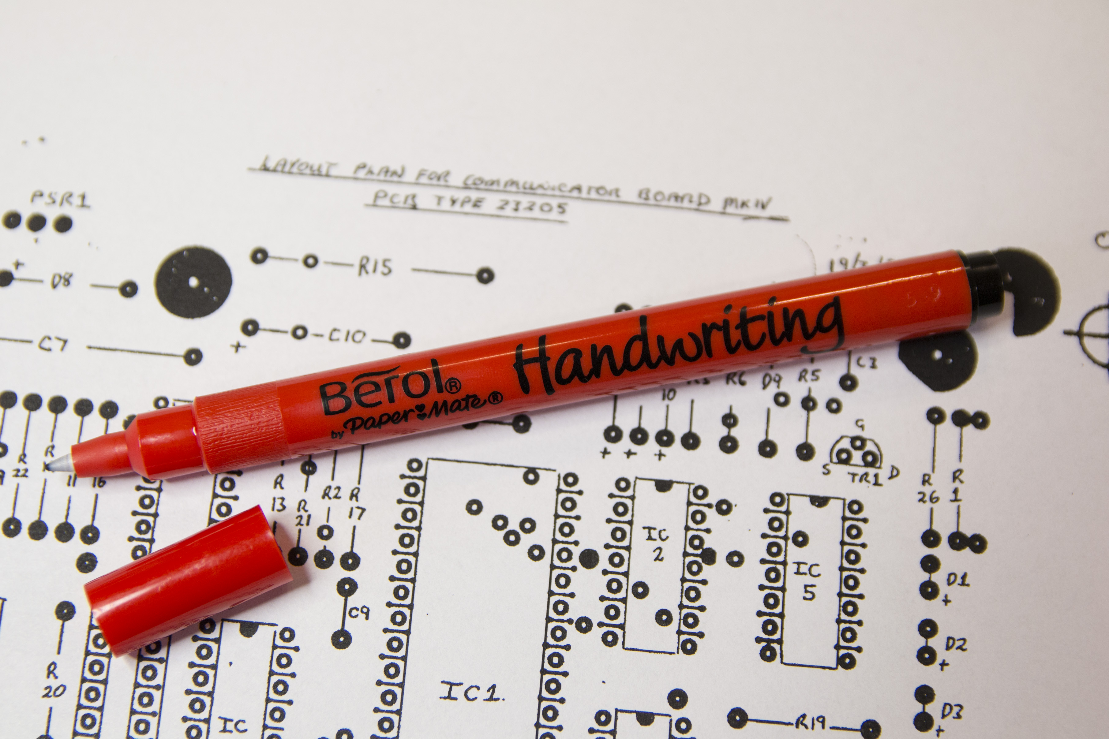
Pen
The Valiant Turtle is designed to use a Berol pen. The pen is held in place by the top of the pen (of which Berol pens have a distinctive design). The correct type of pen (which fits perfectly in the pen holder of the turtle) is shown in the following picture:
Reverse engineering
Purpose
There seems to be far more Valiant Turtle robots available than communicator interfaces as evidenced by many posts from curious owners wondering if the robot can be used without the original interface and sales on sites such as EBay for robots missing the communicator. As the Valiant Turtle communicator Mark II uses a mask-programmed single chip computer (i.e. the programming in ROM was set during manufacture) it is not possible to simply duplicate a circuit schematic in order to create a new controller. The only way to create a new communicator is to reverse engineer a working unit (from the logic perspective as well as circuitry) and then programmatically reproduce the functions of the unit using either a modern computer or microcontroller device (or a combination of the two) with the required electronics for the host communication and infrared link to the turtle. To facilitate such a project (and since I own a complete Valiant Turtle with communicator) I have provided the results of reverse engineering the communicator below.
Communicator Mark II host communication protocol
The Valiant Turtle communicator mark II offers both a serial and 8-bit parallel interface to the host computer. In order to reverse-engineer the communication protocol the Acornsoft Logo programming language was used on a BBC Microcomputer along with the Valiant extensions that allow the programming language to control the physical turtle robot.
Since both the serial and the parallel interfaces use the same 8-bit communication protocol, this reverse-engineering allows either interface to be used towards the host.
The communication protocol is effectively one-way; the exception being the handshaking used by both parallel and serial devices. For serial (RS423/RS232) this is well documented (and the communicator supports between 2400 and 4800 baud with 7N1 and 8N1 byte-length/handshaking).
In the case of the parallel interface the BBC uses the user port’s CB2 line bi-directionally for handshaking. The host pulses CB2 low when a byte is ready for the communicator to receive, and the communicator pulses CB2 low once the byte has been read. This style of handshaking is directly supported by the BBC’s 6522 VIA chip (which acts as the interface between the user port and the BBC’s CPU).
Although both the parallel and serial interfaces support 8-bit communication, the Valiant Turtle communicator mark II only uses 7-bits. The most significant bit is always zero when using either 8-bit parallel or 8-bit serial communication.
On the BBC microcomputer it is possible to communicate directly using BASIC via the user port to the Valiant Turtle communicator. The following BBC BASIC code shows a simple example program that configures the user port correctly and sends bytes to the communicator:
10 MODE 4
20 REM Set user VIA port B to output
30 &FE62 = &FF
40 REM Set VIA port B handshake mode to pulse
50 &FE6C = &A0
60 PRINT “Byte value in decimal?”
70 INPUT byte%
80 REM Send byte to user VIA port B
90 &FE60 = byte%
100 GOTO 60
The first command sent by the host initializes the communicator (and causes the status LED on the communicator to turn off). This command, for compatibility between serial and parallel interfaces is 0b00001101 (0x0D or decimal 13). This is the ASCII code for carriage return (CR). When the ‘FLOOR’ command is sent from Acornsoft logo the host sends two bytes: 0x0D and 0x10 – the second byte is the ‘PENDOWN’ command (this is explained in more detail below).
Analysis of the commands (with the exception of the initialise byte) shows that the 7-bit commands are in fact bit flags that are interpreted by the Turtle’s processor (note that the VT Communicator Mark II does not interpret any commands except the initialise command – all command bytes are passed directly to the IR interface).
The bit flags of the command byte are as follows: AMMPLLRR
- A = This is the most significant bit and is not used (it is also not transferred over the IR link which is 7-bit only)
- MM = This is the motor step sequence indicator and alternates between 10 and 11 in order to step the motors on the turtle
- P = This is the pen state which can either be 0 for pen up or 1 for pen down.
- LL = The left (starboard) motor direction – This can either be 00 for motor off, 10 for motor reverse, 01 for motor forward or 11 for motor on.
- RR = The right (port) motor direction – This can either be 00 for motor off, 01 for motor reverse, 10 for motor forward or 11 for motor on.
Note that the motor direction bits are inverted between the motors. This is because the motors are mounted opposite to each other and therefore the directions are reversed between the motors.
The communication protocol is very basic and for each ‘step’ of the motors there are two commands required, one to start the step and another to stop the step (although both motors can be activated by each command). There is no real ‘command’ for pen up and pen down, this flag can either be set in a separate command, or combined with another command.
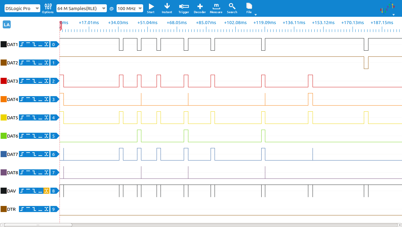
In order to illustrate the commands Acornsoft Logo was used to issue the possible actions of the turtle and the parallel port was monitored using a logic analyser. The typical output from the analyser is shown in the diagram below (this is the activity recorded for the FORWARD 1 command):
The following Logo commands we traced and analysed:
FLOOR command – This command initialises the turtle ready for use and sends two bytes:
- 0b00001101 (initialise with ASCII CR)
- 0b00010000 (Pen down)
PENUP command (places the pen down on the paper)
- 0b00000000 (Pen up)
PENDOWN command (lifts the pen up from the paper)
- 0b00010000 (Pen down)
FORWARD 1 command (move the turtle forward 1 Logo unit)
- 0b00011111 (Pen down, power on left motor, power on right motor)
- 0b01010110 (Motor step stage 1, pen down, left motor forward, right motor forward)
- 0b01110110 (Motor step stage 2, pen down, left motor forward, right motor forward)
- Stage 1 and stage 2 commands are then repeated 2 more times (meaning that 1 Logo unit is 3 motor steps)
- 0b00011111 (Pen down, power on left motor, power on right motor)
- 0b00010000 (Pen down, power off left motor, power off right motor)
BACKWARDS 1 command (move the turtle back 1 Logo unit):
This command is identical to the FORWARD command with the exception of the motor step 1 and 2 commands which are as follows:
- 0b01011001 (Motor step stage 1, pen down, left motor backwards, right motor backwards)
- 0b01111001 (Motor step stage 2, pen down, left motor backwards, right motor backwards)
LEFT 1 command (turn the turtle left 1 degree):
- 0b00011111 (Pen down, power on left motor, power on right motor)
- 0b01010101 (Motor step stage 1, pen down, left motor forward, right motor backwards)
- 0b01110101 (Motor step stage 2, pen down, left motor forward, right motor backwards)
- Stage 1 and stage 2 commands are then repeated 5 more times (meaning that 1 degree is 6 motor steps)
- 0b00011111 (Pen down, power on left motor, power on right motor)
- 0b00010000 (Pen down, power off left motor, power off right motor)
RIGHT 1 command (turn the turtle to the right 1 degree):
As can be imagined, this command is identical to the LEFT command only the left motor is backwards and the right motor is forwards.
Note that Acornsoft Logo (and the Valiant Turtle) support up to 4 turtles controlled by a single communicator. At the time of writing documentation for configuring Logo for multiple turtles was not available. Presumably there is a command or (more likely) a bit pattern in the communication protocol that indicates the required turtle. If possible to recreate, this information will be included in this article at a later point.
Communicator Mark II Infrared protocol
The communicator is responsible for receiving the 7-bit commands from the host and transmitting them to the robot using an infrared link. The infrared link is unmodulated and uses 2.5uS pulses of light to communicate to the robot (note that the link is one-way, communication from the robot to the communicator is not possible). Since the light is a fixed 2-2.5uS pulse the communication is performed by varying the period of the pulses (i.e. the time between sending pulses). This involves the communicator sending a ‘lead-in’ pulse to begin communication, followed by the data and, finally, the lead-out pulses to complete communication.
The IR communication data is a simple copy of the 7-bits received by the communicator from the host; the communicator’s processor does not attempt to interpret the commands before sending, i.e. the communicator will send any bit pattern specified by the host. This fact allows the IR protocol to be reverse engineered by sending sets of known shifting bit patterns to the communicator and analysing the pulse and period output from the infrared transmission stage of the circuitry.
The employed protocol is not a simple ‘mark and space’ style protocol (where one period is used to represent 1 and another for 0). Instead, the communicator uses a programmatic method of encoding that seems to be designed to ensure that the average frame-length of each transmitted byte does not vary too much between bit patterns (i.e. in a simple mark and space protocol the transmission frame-length of 0b0000000 would vary significantly from 0b1111111). In addition, the communication uses a parity indicator as the lead-out pulses, this allows the robot to ensure that it only processes commands that have been reliably received.
The following logic analyser diagram shows the output of P24 (pin 35 of the 80C49 processor) that is connected to the input stage of the infrared transmission circuitry activated by sending a byte with a value of 32 to the communicator:
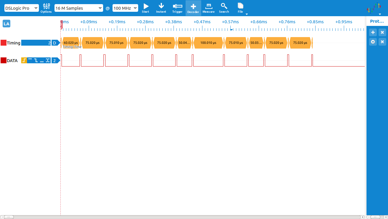
As can be seen from the logic analysis the byte is sent via the infrared interface starting with the least significant bit of the byte.
Since the encoding is programmatic, it is best described using an example program that accepts a 7-bit value (in the normal order of MSB to LSB) and then produces the sequence of period lengths required to transmit the data to the robot over IR. An example of this is given in the C code program below (this can be compiled and run in any GCC environment):
/************************************************************************
    vtIRencoder.c

    Valiant Turtle IR data encoder emulator
    Copyright (C) 2016 Simon Inns

    The Valiant Turtle IR data encoder emulator is free software: you
    can redistribute it and/or modify it under the terms of the GNU
    General Public License as published by the Free Software Foundation,
    either version 3 of the License, or (at your option) any later
    version.

    This program is distributed in the hope that it will be useful,
    but WITHOUT ANY WARRANTY; without even the implied warranty of
    MERCHANTABILITY or FITNESS FOR A PARTICULAR PURPOSE.  See the
    GNU General Public License for more details.

    You should have received a copy of the GNU General Public License
    along with this program.  If not, see .

    Email: simon.inns@gmail.com

************************************************************************/

#include
#include
#include

// This code emulates the Valiant Turtle Communicator Mark II infra-
// red output encoding.  The timing periods are based on the output
// from P24 of the 89C49 processor.  Note that the actual IR pulses
// and periods are slightly different due to the effect of IC2
// (a 4013N flip-flop).

// Function to test if a bit is set to 1 in a byte
bool isBitSet(uint8_t value, uint8_t bitIndex)
{
	return (value & (1 << bitIndex)) != 0;
}

// Function to calculate the parity of a byte
// Returns 0 if parity is odd and 1 if parity is even
uint8_t parity(uint8_t x)
{
   uint8_t y;

   y = x ^ (x >> 1);
   y = y ^ (y >> 2);
   y = y ^ (y >> 4);
   y = y ^ (y >> 8);
   y = y ^ (y >>16);

   return y & 1;
}

// Main function
int main(void)
{
	// The input value between 0 and 127 (7 bits)
	uint8_t value;

	// Pointer to the next bit to transmit
	uint8_t bitPointer;

	// Note: The data is sent LSB first, so transmission is from
	// bit 0 to bit 6 (7-bit data).  Bit 7 should always be 0

	for (value = 0; value < 128; value++)
	{
		// Start of frame
		bitPointer = 0;
		printf("%3d: ", value);

		// Send the lead-in period
		//
		// This is 60 if bit 0 is a 0 or 35 if bit 0 is a 1
		if (isBitSet(value, bitPointer)) printf("35,");
		else printf("60,");

		// Send the data bit periods
		for (bitPointer = 0; bitPointer < 7; bitPointer++)
		{
			// If the current bit is 0 and the next bit is 0 output 75 uS period
			if (isBitSet(value, bitPointer) == 0 && isBitSet(value, bitPointer+1) == 0)
				printf("75,");

			// If the current bit is 0 and the next bit is 1 output 50 uS period
			if (isBitSet(value, bitPointer) == 0 && isBitSet(value, bitPointer+1) == 1)
				printf("50,");

			// If the current bit is 1 and the next bit is 0 output 100 uS period
			if (isBitSet(value, bitPointer) == 1 && isBitSet(value, bitPointer+1) == 0)
				printf("100,");

			// If the current bit is 1 and the next bit is 1 output 75 uS period
			if (isBitSet(value, bitPointer) == 1 && isBitSet(value, bitPointer+1) == 1)
				printf("75,");
		}

		// Send the lead-out periods
		//
		// If the parity is even the lead-out periods are 50, 75 and 75
		// If the parity is odd the lead-out periods are 50, 75 and 100
		if (parity(value) == 1) printf("50,75,75");
		else printf("50,75,100");

		// End of frame
		printf("\r\n");
	}

	return 0;
}
Note that the timing on P24 is not the actual timing of the pulses and periods over the IR link. The transmission circuitry causes the pulses to be around 2-2.5 uS and adds around 5 uS to the period lengths.
Files for download
The original 5.25 inch floppy disc for the BBC Micro was a 40 track single-sided disc and contains some basic test software (that functions only over the serial cable). You can download a copy of the disc below (note: this is in .ssd format for use with Emulators such as BeebEm, although you can convert it back to a physical floppy if you have the required equipment):
With kind permission from Valiant Technologies (who are still in the business of making educational robots) here is a zip file of the Valiant Turtle service manuals:
Valiant Turtle – Service Documentation
The following zip file contains a small number of articles and leaflets about the turtle:
I’m just taking delivery of one of these, minus cables and software: Dave Catlin informed me that you would be the person who would know where I could lay my hands on those.
I don’t think there is really anywhere to buy such cables, but you can make it as there is a wiring diagram (for both the serial and parallel cable) in the article. The software is provided in the ‘downloads’ section.
If you’re using a BBC Micro, then I’ve also scanned and uploaded all of the Acornsoft Logo documentation on the stardot.org.uk forum.
Thanks for the heads up.
I have these cables, plus the software and manuals. I have the manuals for BBC computers, the RM Nimbus 186, and IBM PC compatibles (including the RM Nimbus 286). I have one 3.5 inch floppy, to go with the IBM PC compatibles version, plus one 5.25 floppy version of the software. I think that is for the BBC computers version. I have two cables btw.
I am willing to sell all this gear, if you want to make an offer for it. I gather this stuff is very rare. I have been looking for a haul like the one that I have, but I can’t find anything like this anywhere. Even Ebay is drawing a blank. It seems like all the cables got lost years ago, but lucky me, I have two ;).
If you want to get in contact my email address is patcoyne79@yahoo.co.uk.
By the way, is Dave Catlin the guy that used to be the head of Valiant? I also have a letter from him posted in 1992 apologising for the products being dispatched very late. Poor chap. Maybe that’s why they don’t make these things any more. Ha ha.
So: I have hit the mother-lode and will be taking delivery of a complete Turtle set in about 3 weeks (which is great because I can dissemble my current Turtle that came with no peripherals, with a view to seeing if it can somehow be got to work with a BlueTooth connexion).
However, I can find little or no documentation and any software links to obtain a way to lever it via DOS/Win 3.1 ? ?
I don’t think DOS and Win3.1 is really quite the right era for these robots. You’d have more luck with things like RM Nimbus, BBC Micro and C64. There were PCs around at the time, but they were only in reach of businesses due to the cost. What you find on this page is pretty much *all* of the available documentation, there may be a few more computer specific manuals around, but not much more.
Hi Simon,
I have the PC version of the cable, manual and software. See above for more info. Cheers mate.
Hmm: http://www.valiant-technology.com/archive/usa/turtle1.htm
Finding a link to something pointing at the possibility of software is not quite the same as actually finding something 🙂 If you do find any actual software, then please share the source and I’ll include it here.
http://www.downloadcollection.com/fmslogo.htm
Hi Simon
Great info on the Turtle.
I have a couple of these but no control box.
Any idea where I can get one ?
Please help !!
The control boxes are quite hard to find these days (people kept the turtle but not the control boxes it seems) so ebay is usually the place; they do pop up from time to time.
It’s a bit tricky to make a copy of the original control box since the Philips microcontroller is programmed and a copy of that code is no longer available (so even if you made it, it wouldn’t be easy to program).
It is possible to make a new controller using something like an Arduino though; I’ve not done this myself but there is example code in the article showing how to code the required IR communication (and a breakdown of the protocol is also given) – so if you have Arduino skills (or know someone who does) that could be a viable route.