Commodore SID 6581 Datasheet
Contents
This article is a reproduction of the original Commodore 6581 Sound Interface Device (SID) datasheet. I made this by taking a photocopy of an original document and using OCR to capture the content, then the document was hand-edited, formatted for mediawiki and reassembled here with (cleaned-up and straightened) diagrams and tables.
The reason for this was that most sources on the web are low quality PDFs and, since the documents are graphical copies of the original, they cannot be searched or indexed. The SID chip is a complex device, so I hope anyone developing projects around this device will find this web-based format datasheet useful.
Since it was converted mainly by hand (OCR is not terribly accurate!) I would appreciate it if you could notify me of any errors or omissions you find so I can make this as accurate as possible. If you would like to make a copy of this document please note the Creative Commons licence referenced at the bottom of the page.
Concept
The 6581 Sound Interface Device (SID) is a single-chip, 3-voice electronic music synthesizer/sound effects generator compatible with the 65XX and similar microprocessor families. SID provides wide-range, high-resolution control of pitch (frequency), tone color (harmonic content) and dynamics (volume). Specialized control circuitry minimizes software overhead, facilitating use in arcade/home video games and low-cost musical instruments.
Features
- 3 Tone Oscillators
- Range: 0-4 kHz
- 4 Waveforms per Oscillator
- Triangle
- Sawtooth
- Variable Pulse
- Noise
- 3 Amplitude Modulators
- Range: 48 dB
- 3 Envelope Generators
- Exponential response
- Attack Rate: 2mS-8S
- Decay Rate: 6mS-24S
- Sustain level: 0-peak volume
- Release Rate: 6mS-24S
- Oscillator Synchronization
- Ring Modulation
- Programmable Filter
- Cutoff range: 30 Hz-12 kHz
- 12 dB/octave Rolloff
- Low pass, Band pass, High pass, Notch outputs
- Variable Resonance
- Master Volume Control
- 2 A/D POT Interfaces
- Random Number/Modulation Generator
- External Audio Input
6581 Pin Configuration
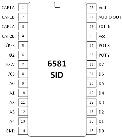
6581 Pin Configuration
Description
The 6581 consists of three synthesizer “voices” which can be used independently or in conjunction with each other (or external audio sources) to create complex sounds. Each voice consists of a Tone Oscillator/Waveform Generator, an Envelope Generator and an Amplitude Modulator. The Tone Oscillator controls the pitch of the voice over a wide range. The Oscillator produces four waveforms at the selected frequency, with the unique harmonic content of each waveform providing simple control of tone color. The volume dynamics of the oscillator are controlled by the Amplitude Modulator under the direction of the Envelope Generator. When triggered, the Envelope Generator creates an amplitude envelope with programmable rates of increasing and decreasing volume. In addition to the three voices, a programmable Filter is provided for generating complex, dynamic tone colors via subtractive synthesis.
SID allows the microprocessor to read the changing output of the third Oscillator and third Envelope Generator. These outputs can be used as a source of modulation information for creating vibrato, frequency/filter sweeps and similar effects. The third oscillator can also act as a random number generator for games. Two A/D converters are provided for interfacing SID with potentiometers. These can be used for “paddles” in a game environment or as front panel controls in a music synthesizer. SID can process external audio signals, allowing multiple SID chips to be daisy-chained or mixed in complex polyphonic systems.
6581 SID Block Diagram
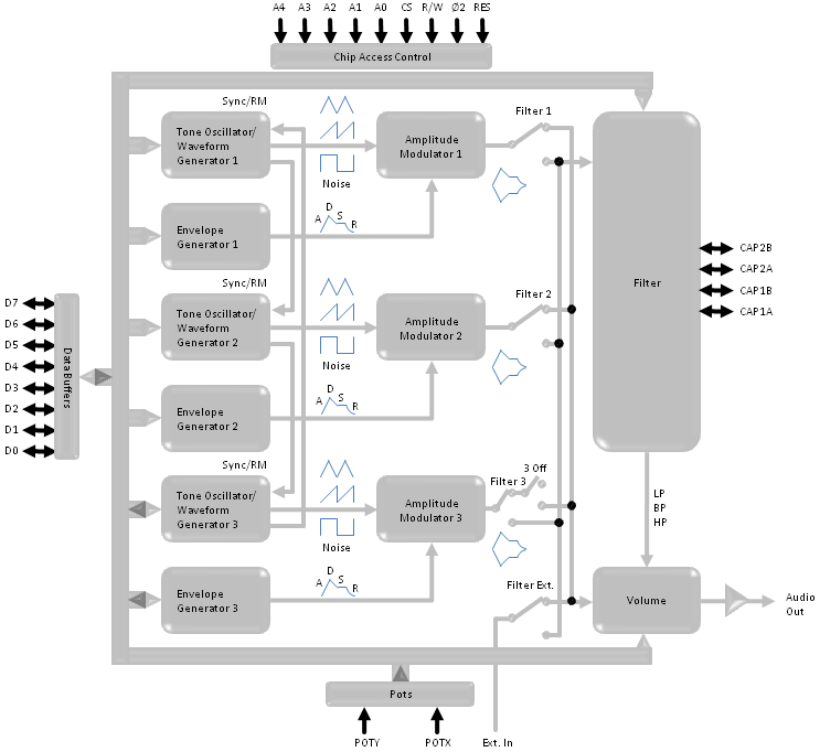
SID Block Diagram
SID Control Registers
There are 29 eight-bit registers in SID which control the generation of sound. These registers are either WRITE-only or READ-only and are listed below in Table 1.
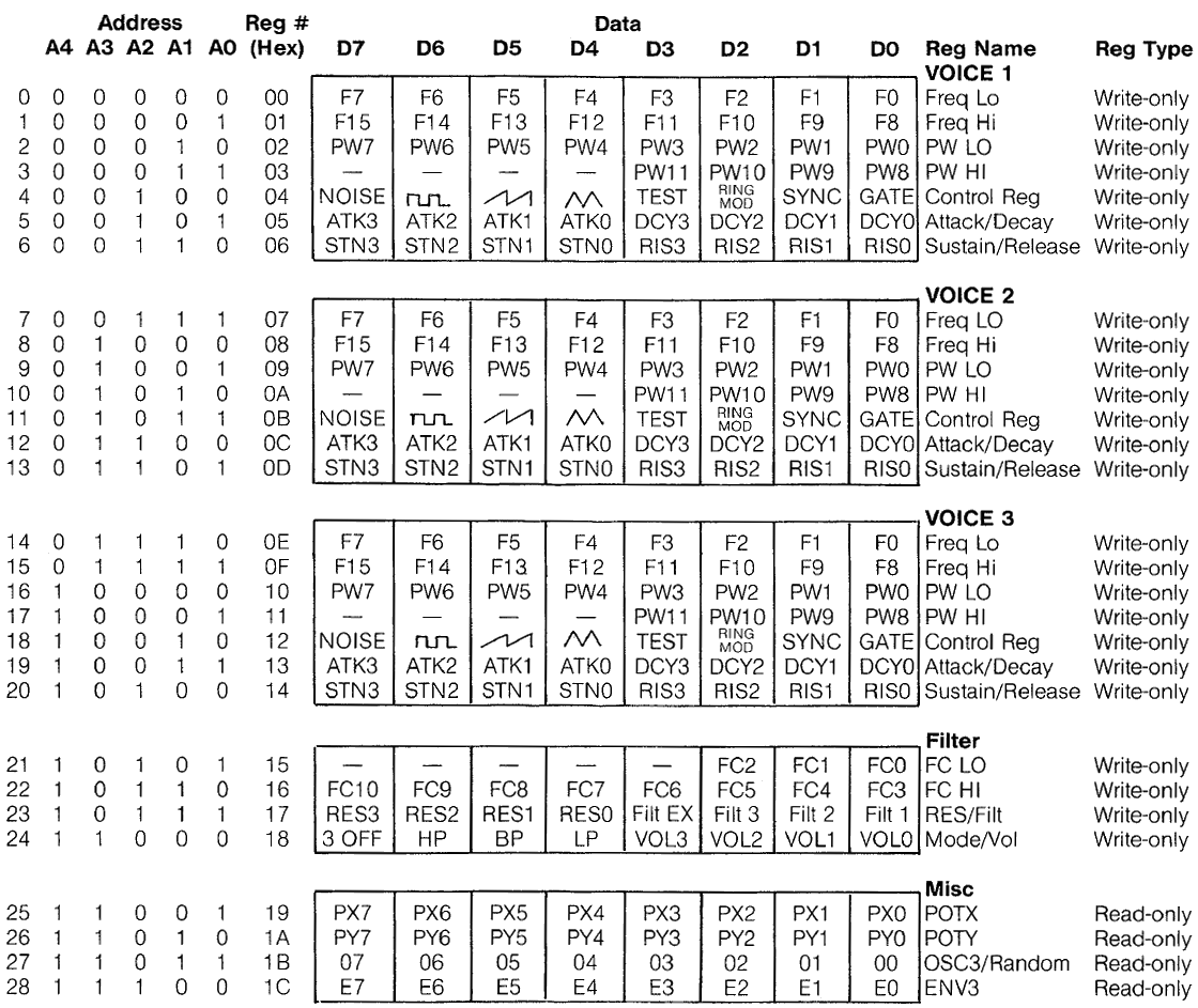
Table 1 – SID Registers
SID Register Description
Voice 1
Freq Lo/Freq Hi (Registers 00-01)
Together these registers form a 16-bit number which linearly controls the Frequency of Oscillator 1. The frequency is determined by the following equation:
Fout = (Fn * Fclk/16777216) Hz
Where Fn is the 16-bit number in the Frequency registers and Fclk is the system clock applied to the Ø2 input (pin 6). For a standard 1.0 Mhz clock, the frequency is given by:
Fout = (Fn * 0.0596) Hz
A complete table of values for generating 8 octaves of the equally-tempered musical scale with concert A (440 Hz) tuning is provided in Commodore SID 6581 Datasheet Appendix A – Equal-Tempered Musical Scale Values. It should be noted that the frequency resolution of SID is sufficient for any tuning scale and allows sweeping from note to note (portamento) with no discernible frequency steps.
PW Lo/PW Hi (Registers 02-03)
Together these registers form a 12-bit number (bits 4-7 of PW Hi are not used) which linearly controls the Pulse Width (duty cycle) of the Pulse waveform on Oscillator 1. The pulse width is determined by the following equation:
PWout = (PWn/40.95) %
Where PWn is the 12-bit number in the Pulse Width registers.
The pulse width resolution allows the width to be smoothly swept with no discernible stepping. Note that the Pulse waveform on Oscillator 1 must be selected in order for the Pulse Width registers to have any audible effect. A value of 0 or 4095 ($FFF) in the Pulse Width registers will produce a constant DC output, while a value of 2048 ($800) will produce a square wave.
Control Register (Register 04)
This register contains eight control bits which select various options on Oscillator 1.
Gate (Bit 0)
The GATE bit controls the Envelope Generator for Voice 1. When this bit is set to a one, the Envelope Generator is Gated (triggered) and the ATTACK/DECAY/SUSTAIN cycle is initiated. When the bit is reset to a zero, the RELEASE cycle begins. The Envelope Generator controls the amplitude of Oscillator 1 appearing at the audio output, therefore, the GATE bit must be set (along with suitable envelope parameters) for the selected output of Oscillator 1 to be audible. A detailed discussion of the Envelope Generator can be found in Commodore SID 6581 Datasheet Appendix B – SID Envelope Generators.
Sync (Bit 1)
The SYNC bit, when set to a one, Synchronizes the fundamental frequency of Oscillator 1 with the fundamental frequency of Oscillator 3, producing “Hard Sync” effects. Varying the frequency of Oscillator 1 with respect to Oscillator 3 produces a wide range of complex harmonic structures from Voice 1 at the frequency of Oscillator 3. In order for sync to occur Oscillator 3 must be set to some frequency other than zero but preferably lower than the frequency of Oscillator 1. No other parameters of Voice 3 have any effect on sync.
Ring Mod (Bit 2)
The RING MOD bit, when set to a one, replaces the Triangle waveform output of Oscillator 1 with a “Ring Modulated” combination of Oscillators 1 and 3. Varying the frequency of Oscillator 1 with respect to Oscillator 3 produces a wide range of non-harmonic overtone structures for creating bell or gong sounds and for special effects. In order for ring modulation to be audible, the Triangle waveform of Oscillator 1 must be selected and Oscillator 3 must be set to some frequency other than zero. No other parameters of Voice 3 have any effect on ring modulation.
Test (Bit 3)
The TEST bit, when set to a one, resets and locks Oscillator 1 at zero until the TEST bit is cleared. The Noise waveform output of Oscillator 1 is also reset and the Pulse waveform output is held at a DC level. Normally this bit is used for testing purposes, however, it can be used to synchronize Oscillator 1 to external events, allowing the generation of highly complex waveforms under real-time software control.
Triangle Wave (Bit 4)
When set to a one, the Triangle waveform output of Oscillator 1 is selected. The Triangle waveform is low in harmonics and has a mellow, flute-like quality.
Sawtooth Wave (Bit 5)
When set to a one, the Sawtooth waveform of Oscillator 1 is selected. The sawtooth waveform is rich in even and odd harmonics and has a bright, brassy quality.
Square Wave (Bit 6)
When set to a one, the Pulse waveform output of Oscillator 1 is selected. The harmonic content of this waveform can be adjusted by the Pulse Width registers, producing tone Qualities ranging from a bright, hollow square wave to a nasal, reedy pulse. Sweeping the pulse width in real-time produces a dynamic “phasing” effect which adds a sense of motion to the sound. Rapidly jumping between different pulse widths can produce interesting harmonic sequences.
Noise (Bit 7)
When set to a one, the Noise output waveform of Oscillator 1 is selected. This output is a random signal which changes at the frequency of Oscillator 1. The sound quality can be varied from a low rumbling to hissing white noise via the Oscillator 1 Frequency registers. Noise is useful in creating explosions, gunshots, jet engines, wind, surf and other un-pitched sounds, as well as snare drums and cymbals. Sweeping the Oscillator frequency with Noise selected produces a dramatic rushing effect. One of the output waveforms must be selected for Oscillator 1 to be audible, however it is NOT necessary to deselect waveforms to silence the output of Voice 1. The amplitude of Voice 1 at the final output is a function of the Envelope Generator only.
NOTE: The oscillator output waveforms are NOT additive. If more than one output waveform is selected simultaneously, the result will be a logical ANDing of the waveforms. Although this technique can be used to generate additional waveforms beyond the four listed above, it must be used with care. If any other waveform is selected while Noise is on, the Noise output can “lock up”. If this occurs, the Noise output will remain silent until reset by the TEST bit or by bringing /RES (pin 5) low.
Attack/Decay (Register 05)
Bits 4-7 of this register (ATK0-ATK3) select 1 of 16 ATTACK rates for the Voice 1 Envelope Generator. The ATTACK rate determines how rapidly the output of Voice 1 rises from zero to peak amplitude when the Envelope Generator is Gated. The 16 ATTACK rates are listed below in Table 2.
Bits 0-3 (DCY0-DCY3) select 1 of 16 DECAY rates for the Envelope Generator. The DECAY cycle follows the ATTACK cycle and the DECAY rate determines how rapidly the output falls from the peak amplitude to the selected SUSTAIN level. The 16 DECAY rates are listed in Table 2.
| Attack Rate | Release Rate | ||
|---|---|---|---|
| DEC | HEX | (Time/Cycle) | (Time/Cycle) |
| 0 | (0) | 2 mS | 6 mS |
| 1 | (1) | 8 mS | 24 mS |
| 2 | (2) | 16 mS | 48 mS |
| 3 | (3) | 24 mS | 72 mS |
| 4 | (4) | 38 mS | 114 mS |
| 5 | (5) | 56 mS | 168 mS |
| 6 | (6) | 68 mS | 204 mS |
| 7 | (7) | 80 mS | 240 mS |
| 8 | (8) | 100 mS | 300 mS |
| 9 | (9) | 250 mS | 750 mS |
| 10 | (A) | 500 mS | 1.5 S |
| 11 | (B) | 800 mS | 2.4 S |
| 12 | (C) | 1 S | 3 S |
| 13 | (D) | 3 S | 9 S |
| 14 | (E) | 5 S | 15 S |
| 15 | (F) | 8 S | 24 S |
Table 2: Commodore SID 6581 Decay Rates
NOTE: Envelope rates are based on a 1.0 Mhz Ø2 clock. For other Ø2 frequencies, multiply the given rate by 1 Mhz / Ø2. The rates refer to the amount of time per cycle. For example, given an ATTACK value of 2, the ATTACK cycle would take 16 mS to rise from zero to peak amplitude. The DECAY/RELEASE rates refer to the amount of time these cycles would take to fall from peak amplitude to zero.
Sustain/Release (Register 06)
Bits 4-7 of this register (STN0-STN3) select 1 of 16 SUSTAIN levels for the Envelope Generator. The SUSTAIN cycle follows the DECAY cycle and the output of Voice 1 will remain at the selected SUSTAIN amplitude as long as the Gate bit remains set. The SUSTAIN levels range from zero to peak amplitude in 16 linear steps, with a SUSTAIN value of 0 selecting zero amplitude and a SUSTAIN value of 15 (#F) selecting the peak amplitude.
A SUSTAIN value of 8 would cause Voice 1 to SUSTAIN at an amplitude one-half the peak amplitude reached by the ATTACK cycle.
Bits 0-3 (RLS0-RLS3) select 1 of 16 RELEASE rates for the Envelope Generator. The RELEASE cycle follows the SUSTAIN cycle when the Gate bit is reset to zero. At this time, the output of Voice 1 will fall from the SUSTAIN amplitude to zero amplitude at the selected RELEASE rate. The 16 RELEASE rates are identical to the DECAY rates.
NOTE: The cycling of the Envelope Generator can be altered at any point via the Gate bit. The Envelope Generator can be Gated and Released without restriction. For example, if the Gate bit is reset before the envelope has finished the ATTACK cycle, the RELEASE cycle will immediately begin, starting from whatever amplitude had been reached. If the envelope is then Gated again (before the RELEASE cycle has reached zero amplitude), another ATTACK cycle will begin, starting from whatever amplitude had been reached. This technique can be used to generate complex amplitude envelopes via real-time software control.
Voice 2
Registers 07-$0D control Voice 2 and are functionally identical to registers 00-06 with these exceptions:
When selected, SYNC synchronizes Oscillator 2 with Oscillator 1.
When selected, RING MOD replaces the Triangle output of Oscillator 2 with the ring modulated combination of Oscillators 2 and 1.
Voice 3
Registers $0E-$14 control Voice 3 and are functionally identical to registers 00-06 with these exceptions:
When selected, SYNC synchronizes Oscillator 3 with Oscillator 2.
When selected, RING MOD replaces the Triangle output of Oscillator 3 with the ring modulated combination of Oscillators 3 and 2.
Typical operation of a voice consists of selecting the desired parameters: frequency, waveform effects (SYNC, RING MOD) and envelope rates, then gating the voice whenever the sound is desired. The sound can be sustained for any length of time and terminated by clearing the Gate bit. Each voice can be used separately, with independent parameters and gating, or in unison to create a single, powerful voice. When used in unison, a slight detuning of each oscillator or tuning to musical intervals creates a rich, animated sound.
Filter
FC Lo/FC Hi (Registers $15, $16)
Together these registers form an 11-bit number (bits 3-7 of FC LO are not used) which linearly controls the Cutoff (or Center) Frequency of the programmable Filter. The approximate Cutoff Frequency ranges between 30Hz and 10KHz with the recommended capacitor values of 2200pF for CAP1 and CAP2.
The frequency range of the Filter can be altered to suit specific applications. Refer to the Pin Description section for more information.
RES/Filt (Register $17)
Bits 4-7 of this register (RES0-RES3) control the Resonance of the Filler, resonance of a peaking effect which emphasizes frequency components at the Cutoff Frequency of the Filter, causing a sharper sound. There are 16 Resonance settings ranging linearly from no resonance (0) to maximum resonance (15 or #F).
Bits 0-3 determine which signals will be routed through the Filter:
Filt 1 (Bit 0)
When set to a zero, Voice 1 appears directly at the audio output and the Filter has no effect on it. When set to a one, Voice 1 will be processed through the Filter and the harmonic content of Voice 1 will be altered according to the selected Filter parameters.
Filt 2 (Bit 1)
Same as bit 0 for Voice 2.
Filt 3 (Bit 2)
Same as bit 0 for voice 3.
Filtex (Bit 3)
Same as bit 0 for External audio input (pin 26).
Mode/Vol (Register $18)
Bits 4-7 of this register select various Filter mode and output options:
LP (Bit 4)
When set to a one, the low Pass output of the Filter is selected and sent to the audio output. For a given Filter input Signal, all frequency components below the Filter Cutoff Frequency are passed unaltered, while all frequency components above the Cutoff are attenuated at a rate of 12 dB/Octave. The low Pass mode produces full-bodied sounds.
BP (Bit 5)
Same as bit 4 for the Band Pass output. All frequency components above and below the Cutoff are attenuated at a rate of 6 dB/Octave. The Band Pass mode produces thin, open sounds.
HP (Bit 6)
Same as bit 4 for the High Pass output. All frequency components above the Cutoff are passed unaltered, while all frequency components below the Cutoff are attenuated at a rate of 12 dB/Octave. The High Pass mode produces tinny, buzzy sounds.
3 OFF (Bit 7)
When set to a one, the output of Voice 3 is disconnected from the direct audio path. Setting Voice 3 to bypass the Filter (FILT 3 = 0) and selling 3 OFF to a one prevents Voice 3 from reaching the audio output. This allows Voice 3 to be used for modulation purposes without any undesirable output.
NOTE: The Filter output modes ARE additive and multiple Filter modes may be selected simultaneously.
For example, both LP and HP modes can be selected to produce a Notch (or Band Reject) Filter response. In order for the Filter to have any audible effect, at least one Filter output must be selected and at least one Voice must be routed through the Filter. The Filter is, perhaps, the most important element in SID as it allows the generation of complex tone colors via subtractive synthesis. The Filter is used to eliminate specific frequency components from a harmonically-rich input signal). The best results are achieved by varying the Cutoff Frequency in real-time.
Bits 0-3 (VOL0-VOL3) select 1 of 16 overall Volume levels for the final composite audio output. The output volume levels range from no output (0) to maximum volume (15 or #F) in 16 linear steps. This control can be used as a static volume control for balancing levels in multi-chip systems or for creating dynamic volume effects, such as Tremolo. Some Volume level other than zero must be selected in order for SID to produce any sound.
Misc
POTX (Register $19)
This register allows the microprocessor to read the position of the potentiometer tied to POTX (pin 24), with values ranging from 0 at minimum resistance, to 255 (#FF) at maximum resistance. The value is always valid and is updated every 512 Ø2 clock cycles. See the Pin Description section for information on post and capacitor values.
POTY (Register $1A)
Same as POTX for the pot tied to POTY (pin 23).
OSC 3/RANDOM (Register $1B)
This register allows the microprocessor to read the upper 8 output bits of Oscillator 3. The character of the numbers generated is directly related to the waveform selected. If the Sawtooth waveform of Oscillator 3 is selected, this register will present a series of numbers incrementing from 0 to 255 ($FF) at a rate determined by the frequency of Oscillator 3. If the Triangle waveform is selected, the output will increment from 0 up to 255, then decrement down to 0. If the Pulse waveform is selected, the output will jump between 0 and 255. Selecting the Noise waveform will produce a series of random numbers, therefore, this register can be used as a random number generator for games. There are numerous timing and sequencing applications for the OSC 3 register, however, the chief function is probably that of a modulation generator. The numbers generated by this register can be added, via software, to the Oscillator or Filter Frequency registers or the Pulse Width registers in real-time. Many dynamic effects can be generated in this manner. Siren-like sounds can be created by adding the OSC 3 Sawtooth output to the frequency control of another oscillator. Synthesizer “Sample and Hold” effects can be produced by adding the OSC 3 Noise output to the Filter Frequency control registers. Vibrato can be produced by selling Oscillator 3 to a frequency around 7 Hz and adding the OSC 3 Triangle output (with proper scaling) to the Frequency control of another oscillator. An unlimited range of effects are available by altering the frequency of Oscillator 3 and scaling the OSC 3 output. Normally, when Oscillator 3 is used for modulation, the audio output of Voice 3 should be eliminated (3 OFF = 1).
ENV 3 (Register $1C)
Same as OSC 3, but this register allows the microprocessor to read the output of the Voice 3 Envelope Generator. This output can be added to the Filler Frequency to produce harmonic envelopes, WAH WAH, and similar effects. “Phaser” sounds can be created by adding this output to the frequency control registers of an oscillator. The Voice 3 Envelope Generator must be gated in order to produce any output from this register. The OSC 3 register, however, always reflects the changing output of the oscillator and is not affected in any way by the Envelope Generator.
SID Pin Description
CAP1A, CAP1B (Pins 1,2)/CAP2A, CAP2B Pins 3,4)
These pins are used to connect the two integrating capacitors required by the programmable Filter. C1 connects between pins 1 and 2, C2 between pins 3 and 4. Both capacitors should be the same value. Normal operation of the Filter over the audio range (approximately – 30 Hz-12 KHz) is accomplished with a value of 2200 pF for C1 and C2. Polystyrene capacitors are preferred. In complex polyphonic systems, where many SID chips must track each other, matched capacitors are recommended. The frequency range of the Filter can be tailored to specific applications by the choice of capacitor values. For example, a low-cost game may not require full high-frequency response, In this case, larger values for C1 and C2 could be chosen to provide more control over the bass frequencies of the Filter. The approximate maximum Cutoff Frequency of the Filter is given by:
FCmax = 2.6E-5/C
Where C is the capacitor value. The range of the Filter extends approximately 9 octaves below the maximum Cutoff Frequency.
/RES (Pin 5) -This TTL-level input is the reset control for SID. When brought low for at least ten Ø2 cycles, all internal registers are reset to zero and the audio output is silenced. This pin is normally connected to the reset line of the microprocessor or a power-on-clear circuit.
Ø2 (Pin 6) -This TTL-level input is the master clock for SID. All oscillator frequencies and envelope rates are referenced to this clock. Ø2 also controls data transfers between SID and the microprocessor. Data can only be transferred when Ø2 is high. Essentially, Ø2 acts as a high-active chip select as far as data transfers are concerned. This pin is normally connected to the system clock, with a nominal operating frequency of 1.0 MHz.
R/W (Pin 7) -This TTL-level input controls the direction of data transfers between SID and the microprocessor. If the chip select conditions have been met, a high on this line allows the microprocessor to Read data from the selected SID register and a low allows the microprocessor to Write data into the selected SID register. This pin is normally connected to the system Read/Write line.
/CS (Pin 8) -This TTL-level input is a low active Chip select which controls data transfers between SID and the microprocessor. /CS must be low for any transfer. A Read from the selected SID register can only occur if /CS is low, Ø2 is high and R/W is high. A Write to the selected SID register can only occur if /CS is low, Ø2 is high and R/W is low. This pin is normally connected to address decoding circuitry, allowing SID to reside in the memory map of a system.
A0-A4 (Pins 9-13) -These TTL-level inputs are used to select one of the 29 SID registers. Although enough addresses are provided to select 1 of 32 registers, the remaining three register locations are not used. A Write to any of these three locations is ignored and a Read returns invalid data. These pins are normally connected to the corresponding address lines of the microprocessor so that SID may be addressed in the same manner as memory.
GND (Pin 14) -For best results, the ground line between SID and the power supply should be separate from ground tines to other digital circuitry. This will minimize digital noise at the audio output.
D0-D7 (Pins 15-22) -These bidirectional lines are used to transfer data between SID and the microprocessor. They are TTL compatible in the output mode and capable of driving 2 TTL loads in the output mode. The data buffers are usually in the high-impedance off state. During a Write operation, the data buffers remain in the off (input) state and the microprocessor supplies data to SID over these lines. During a Read operation, the data buffers turn on and SID supplies data to the microprocessor over these lines. The pins are normally connected to the corresponding data lines of the microprocessor.
POTX, POTY (Pins 24, 23) -These pins are inputs to the A/D converters used to digitize the position of potentiometers. The conversion process is based on the time constant of a capacitor tied from the POT pin to ground, charged by a potentiometer tied from the POT pin to +5 volts. The component values are determined by
RC = 4.7E-4
Where R is the maximum resistance of the pot and C is the capacitor.
The larger the capacitor, the smaller the POT value jitter. The recommended values for R and C are 470 KOhms and 1000 pF.
Note that a separate pot and cap are required for each POT pin.
Vcc (Pin 25) – As with the GND line, a separate +5 VDC line should be run between SID Vcc and the power supply in order to minimize noise. A bypass capacitor should be located close to the pin.
Ext In (Pin 26) -This analog input allows external audio signals to be mixed with the audio output of SID or processed through the Filter. Typical sources include voice, guitar and organ. The input impedance of this pin is in the order of 100 KOhms. Any signal applied directly to the pin should ride at DC level of 6 volts and should not exceed 3 volts p-p. In order to prevent any interference caused by DC level differences, external signals should be AC-coupled to EXT IN by an electrolytic capacitor in the 1-10uF range. As the direct audio path (FILTEX = 0) has unity gain, EXT IN can be used to mix outputs of many SID chips by daisy-chaining. The number of chips that can be chained in this manner is determined by the amount of noise and distortion allowable at the final output. Note that the output Volume control will affect not only the three SID voices, but also any external inputs.
Audio Out (Pin 27) -This open-source buffer is the final audio output of SID, comprised of the three SID voices, the Filter and any external input. The output level is set by the output Volume control and reaches a maximum of approximately 3 volts p-p at a 6 volt DC level. A source resistor from AUDIO OUT to ground is required for proper operation. The recommended resistance is 1 KOhm for a standard output impedance. As the output of SID rides at a 6 volt DC level, it should be AC-coupled to any audio amplifier with an electrolytic capacitor in the 1-10uF range.
Vdd (Pin 28) – As with Vcc, a separate + 12 VDC fine should be run to SID Vdd and a bypass capacitor should be used.
See Commodore SID 6581 Datasheet Appendix C – Typical 6581 SID Application for typical SID application.
6581 SID Characteristics
Absolute Maximum Ratings
- Supply Voltage, Vdd -0.3 VDC to +17 VDC
- Supply Voltage, Vcc -0.3 VDC to +7 VDC
- Input Voltage (analog). Vina -0.3 VDC to +17 VDC
- Input Voltage (digital), Vind -0.3 VDC to +7 VDC
- Operating Temperature, Ta 0° C to +70° C
- Storage Temperature, Tstg -55° C to +150° C
All inputs contain protection circuitry to prevent damage due to high static discharges. Care should be exercised to prevent unnecessary application of voltages in excess of the allowable limits.
Comment
Stresses above those listed under “Absolute Maximum Ratings” may cause permanent damage to the device. These are stress ratings only. Functional operation of this device at these or any other conditions above those indicated in the operational sections of this specification is not implied and exposure to absolute maximum rating conditions for extended periods may affect device reliability.
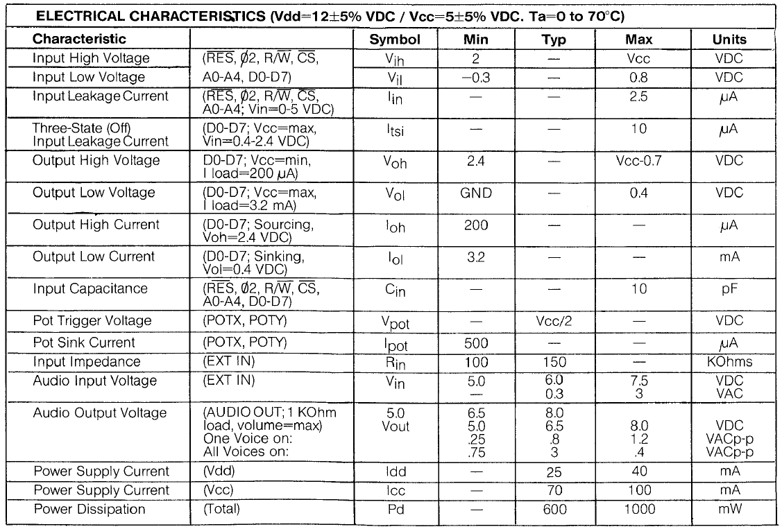
Electrical Characteristics
6581 (SID) Timing
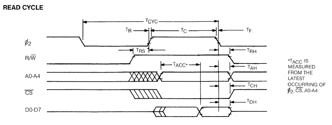
SID Timing READ
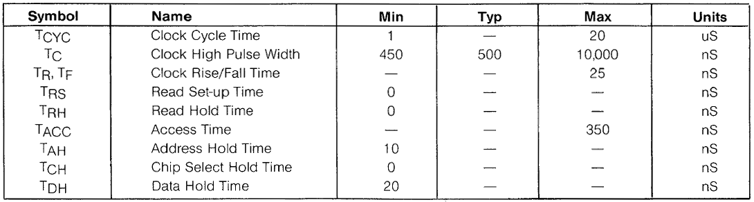
Read cycle table
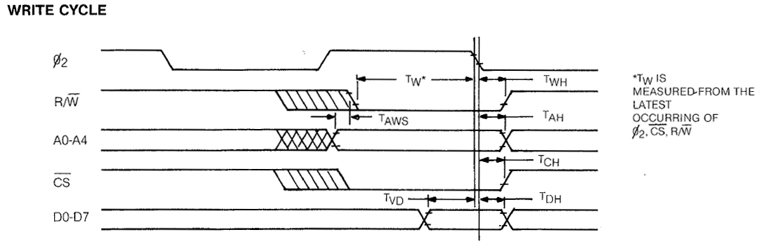
SID Timing WRITE
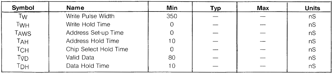
Write cycle table
Appendix A – Equal-Tempered Musical Scale Values
The following table lists the numerical values which must be stored in the SID Oscillator frequency control registers to produce the notes of the equal-tempered musical scale. The equal-tempered scale consists of an octave containing 12 semitones (notes): C, D, E, F, G, A, B and C#, D#, F#, G#, A#. The frequency of each semitone is exactly the 12th root of 2 times the frequency of the previous semitone. The table is based on a Ø2 = clock of 1.0 Mhz. Refer to the equation given in the Register Description for use of other master clock frequencies. The scale selected is concert pitch, in which A4 = 440 Hz. Transpositions of this scale and scales other than the equal-tempered scale are also possible.
| Musical Note | Freq | Osc Fn | Osc Fn | Musical Note | Freq | Osc Fn | Osc Fn | ||
|---|---|---|---|---|---|---|---|---|---|
| (Hz) | (Decimal) | (Hex) | (Hz) | (Decimal) | (Hex) | ||||
| 0 | C0 | 16.35 | 274 | 0112 | 48 | C4 | 261.63 | 4389 | 1125 |
| 1 | C0$ | 17.32 | 291 | 0123 | 49 | C4$ | 277.18 | 4650 | 122A |
| 2 | D0 | 18.35 | 308 | 0134 | 50 | D4 | 293.66 | 4927 | 133F |
| 3 | D0$ | 19.44 | 326 | 0146 | 51 | D4$ | 311.13 | 5220 | 1464 |
| 4 | E0 | 20.60 | 346 | 015A | 52 | E4 | 329.63 | 5530 | 159A |
| 5 | F0 | 21.83 | 366 | 016E | 53 | F4 | 349.23 | 5859 | 16E3 |
| 6 | F0$ | 23.12 | 388 | 0184 | 54 | F4$ | 370.00 | 6207 | 183F |
| 7 | G0 | 24.50 | 411 | 018B | 55 | G4 | 392.00 | 6577 | 1981 |
| 8 | G0$ | 25.96 | 435 | 01B3 | 56 | G4$ | 415.30 | 6968 | 1B38 |
| 9 | A0 | 27.50 | 461 | 01CD | 57 | A4 | 440.00 | 7382 | 1CD6 |
| 10 | A0$ | 29.14 | 489 | 01E9 | 58 | A4$ | 466.16 | 7821 | 1E80 |
| 11 | B0 | 30.87 | 518 | 0206 | 59 | B4 | 493.88 | 8286 | 205E |
| 12 | C1 | 32.70 | 549 | 0225 | 60 | C5 | 523.25 | 8779 | 224B |
| 13 | C1$ | 34.65 | 581 | 0245 | 61 | C5$ | 554.37 | 9301 | 2455 |
| 14 | D1 | 36.71 | 616 | 0268 | 62 | D5 | 587.33 | 9854 | 267E |
| 15 | D1$ | 38.89 | 652 | 028C | 63 | D5$ | 622.25 | 10440 | 28C8 |
| 16 | E1 | 41.20 | 691 | 02B3 | 64 | E5 | 659.25 | 11060 | 2B34 |
| 17 | F1 | 43.65 | 732 | 02DC | 65 | F5 | 698.46 | 11718 | 2DC6 |
| 18 | F1$ | 46.25 | 776 | 0308 | 66 | F5$ | 740.00 | 12415 | 307F |
| 19 | G1 | 49.00 | 822 | 0336 | 67 | G5 | 783.99 | 13153 | 3361 |
| 20 | G1$ | 51.91 | 871 | 0367 | 68 | G5$ | 830.61 | 13935 | 366F |
| 21 | A1 | 55.00 | 923 | 039B | 69 | A5 | 880.00 | 14764 | 39AC |
| 22 | A1$ | 58.27 | 978 | 03D2 | 70 | A5$ | 932.33 | 15642 | 3D1A |
| 23 | B1 | 61.74 | 1036 | 040C | 71 | B5 | 987.77 | 16572 | 40BC |
| 24 | C2 | 65.41 | 1097 | 0449 | 72 | C6 | 1046.50 | 17557 | 4495 |
| 25 | C2$ | 69.30 | 1163 | 048B | 73 | C6$ | 1108.73 | 18601 | 48A9 |
| 26 | D2 | 73.42 | 1232 | 04D0 | 74 | D6 | 1174.66 | 19709 | 4CFC |
| 27 | D2$ | 77.78 | 1305 | 0519 | 75 | D6$ | 1244.51 | 20897 | 518F |
| 28 | E2 | 82.41 | 1383 | 0567 | 76 | E6 | 1381.51 | 22121 | 5669 |
| 29 | F2 | 87.31 | 1465 | 05B9 | 77 | F6 | 1396.91 | 23436 | 5B8C |
| 30 | F2$ | 92.50 | 1552 | 0610 | 78 | F6$ | 1479.98 | 24830 | 60FE |
| 31 | G2 | 98.00 | 1644 | 066C | 79 | G6 | 1567.98 | 26306 | 6602 |
| 32 | G2$ | 103.83 | 1742 | 06CE | 80 | G6$ | 1661.22 | 27871 | 6CDF |
| 33 | A2 | 110.00 | 1845 | 0735 | 81 | A6 | 1760.00 | 29528 | 7358 |
| 34 | A2$ | 116.54 | 1955 | 07A3 | 82 | A6$ | 1864.65 | 31234 | 7A34 |
| 35 | B2 | 123.47 | 2071 | 0817 | 83 | B6 | 1975.53 | 33144 | 8178 |
| 36 | C3 | 130.81 | 2195 | 0893 | 84 | C7 | 2093.00 | 35115 | 892B |
| 37 | C3$ | 138.59 | 2325 | 0915 | 85 | C7$ | 2217.46 | 37203 | 9153 |
| 38 | D3 | 146.83 | 2463 | 099F | 86 | D7 | 2349.32 | 39415 | 99F7 |
| 39 | D3$ | 155.56 | 2610 | 0A32 | 87 | D7$ | 2489.01 | 41759 | A31F |
| 40 | E3 | 164.81 | 2765 | 0ACD | 88 | E7 | 2637.02 | 44242 | ACD2 |
| 41 | F3 | 174.61 | 2930 | 0B72 | 89 | F7 | 2793.83 | 46873 | B719 |
| 42 | F3$ | 185.00 | 3104 | 0C20 | 90 | F7$ | 2959.95 | 49660 | C1FC |
| 43 | G3 | 196.00 | 3288 | 0CD8 | 91 | G7 | 3135.96 | 52613 | CD85 |
| 44 | G3$ | 207.65 | 3484 | 0D9C | 92 | G7$ | 3322.44 | 55741 | D9BD |
| 45 | A3 | 220.00 | 3691 | 0E6B | 93 | A7 | 3520.00 | 59056 | E6B0 |
| 46 | A3$ | 233.08 | 3910 | 0F46 | 94 | A7$ | 3729.31 | 62567 | F467 |
| 47 | B3 | 246.94 | 4143 | 102F | 95 | B7 | 3951.06 | 66288 | 102F0 |
Commodore SID 6581 Equal-Tempered Musical Scale
Although the table above provides a simple and quick method for generating the equal-tempered scale, it is very memory inefficient as it requires 192 bytes for the table alone. Memory efficiency can be improved by determining the note value algorithmically. Using the fact that each note in an octave is exactly half the frequency of that note in the next octave, the note look-up table can be reduced from 96 entries to 12 entries, as there are 12 notes per octave. If the 12 entries (24 bytes) consist of the 16-bit values for the eighth octave (C7 through B7), then notes in lower octaves can be derived by choosing the appropriate note in the eighth octave and dividing the 16-bit value by two for each octave of difference. As division by two is nothing more than a right-shift of the value, the calculation can easily be accomplished by a simple software routine. Although note B7 is beyond the range of the Oscillators this value should still be included in the table for calculation purposes (the MSB of B7 would require a special software case, such as generating this bit in the CARRY before shifting). Each note must be specified in a form which indicates which of the 12 semitones is desired, and which of the eight octaves the semitone is in. Since four bits are necessary to select 1 of 12 semitones and three bits are necessary to select 1 of 8 octaves, the information can fit in one byte, with the lower nybble selecting the semitone (by addressing the look-up table) and the upper nybble being used by the division routine to determine how many times the table value must be right-shifted.
Appendix B – SID Envelope Generators
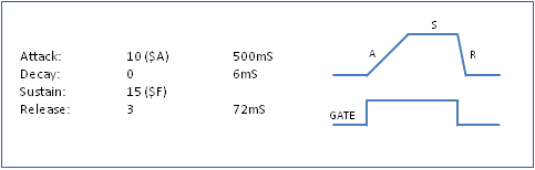
The four-part ADSR (ATTACK, DECAY, SUSTAIN, RELEASE) envelope generator has been proven in electronic music to provide the optimum trade-off between flexibility and ease of amplitude control. Appropriate selection of envelope parameters allows the simulation of a wide range of percussion and sustained instruments. The violin is a good example of a sustained instrument. The violinist controls the volume by bowing the instrument. Typically, the volume builds slowly, reaches a peak, then drops to an intermediate level. The violinist can maintain this level for as long as desired, then the volume is allowed to slowly die away. A “snapshot” of this envelope is shown below:
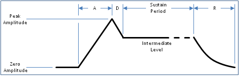
SID Envelope 1
This volume envelope can be easily reproduced by the ADSR as shown below, with typical envelope rates:
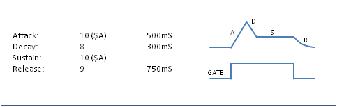
SID envelope 2
Note that the tone can be held at the intermediate SUSTAIN level for as long as desired. The tone will not begin to die away until GATE is cleared. With minor alterations, this basic envelope can be used for brass and woodwinds as well as strings.
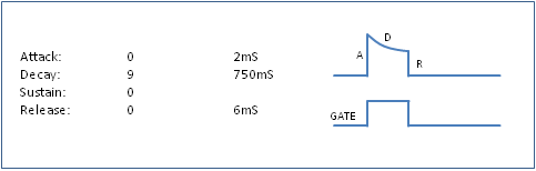
An entirely different form of envelope is produced by percussion instruments such as drums, cymbals and gongs, as well as certain keyboards such as pianos and harpsichords. The percussion envelope is characterized by a nearly instantaneous attack, immediately followed by a decay to zero volume. Percussion instruments cannot be sustained at a constant amplitude. For example, the instant a drum is struck, the sound reaches full volume and decays rapidly regardless of how it was struck. A typical cymbal envelope is shown below:
SID Envelope 3
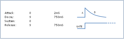
Note that the tone immediately begins to decay to zero amplitude after the peak is reached, regardless of when GATE is cleared. The amplitude envelope of pianos and harpsichords is somewhat more complicated, but can be generated quite easily with the ADSR. These instruments reach full volume when a key is first struck. The amplitude immediately begins to die away slowly as long as the key remains depressed. If the key is released before the sound has fully died away, the amplitude will immediately drop to zero. This envelope is shown below:
SID Envelope 4
Note that the tone decays slowly until GATE is cleared, at which point the amplitude drops rapidly to zero.
The most simple envelope is that of the organ. When a key is pressed, the tone immediately reaches full volume and remains there. When the key is released, the tone drops immediately to zero volume. This envelope is shown below:
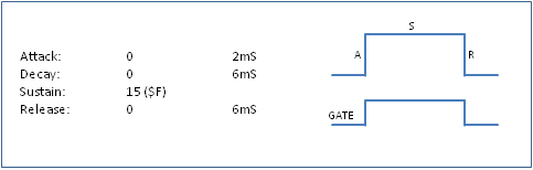
SID Envelope 5
The real power of SID lies in the ability to create original sounds rather than simulations of acoustic instruments. The ADSR is capable of creating envelopes which do not correspond to any “real” instruments. A good example would be the “backwards” envelope. This envelope is characterized by a slow attack and rapid decay which sounds very much like an instrument that has been recorded on tape then played backwards. This envelope is shown below:
SID Envelope 6
Many unique sounds can be created by applying the amplitude envelope of one instrument to the harmonic structure of another. This produces sounds similar to familiar acoustic instruments, yet notably different. In general, sound is quite subjective and experimentation with various envelope rates and harmonic contents will be necessary in order to achieve the desired sound.
Appendix C – Typical 6581 SID Application
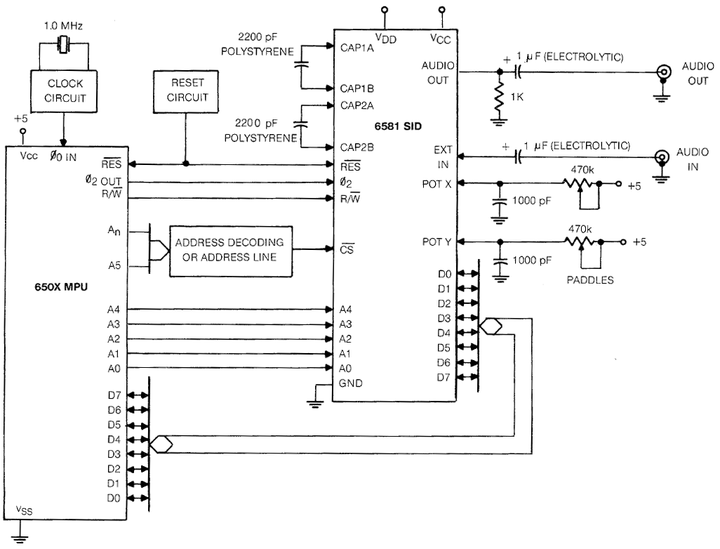
SID Typical Application