RGB Luxeon Star Mood Light
Contents
The Luxeon Star RGB Mood Lamp requires a 9V DC power supply with at least 1500mA. The connection to the lamp is a 2.1mm DC jack which should be centre positive. The jack should be inserted into the lamp and the lamp assembled before plugging the power supply into the mains socket.
The light can be removed from the glass dome by turning the lamp upside-down and squeezing the two metal springs. The light should be removed very carefully to avoid unwanted damage. Avoid placing your fingers on or underneath the circuit boards (the components are ESD sensitive and can be destroyed by static electricity).
The power regulation circuitry in the lamp runs at around 30-50C, failure to assemble the lamp before powering it may result in burns.
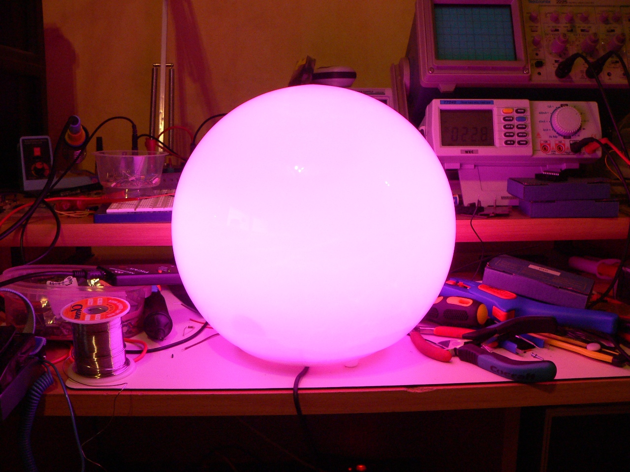
Once powered the lamp will run quickly through a test sequence, this is red, green then blue (for 2 seconds each), then the lamp cycles through the available 37 colour mixes displaying each one for half a second. The lamp will then turn off for 1 second and then start displaying the first colour. Each colour is displayed for 30 seconds.
Tthe lamp’s casing is a FADO globe light which can be purchased from Ikea:
FADO Bordslampa, artikelnummer: 80096372
The LED lights in the lamp should last for around 50,000 – 80,000 hours of use.
How does it work?
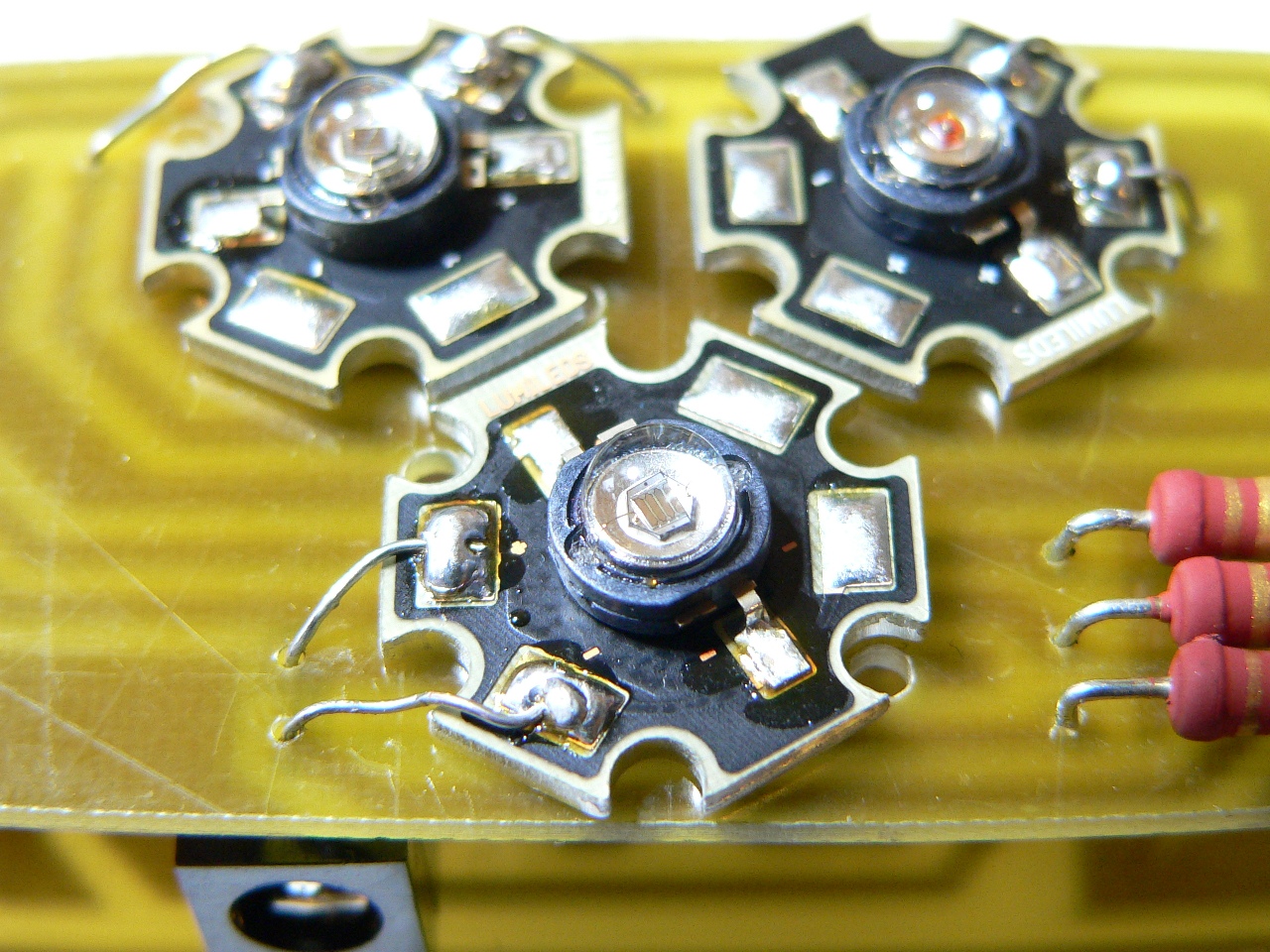
The lamp contains 3 Luxeon Star LED lights, red, green and blue. Each light uses around 1 Watt maximum, so the lamp is very energy efficient (it typically consumes 40-60 times less electricity than a standard incandescent light bulb).
A small ‘single-chip’ computer is used to control the LEDs (Microchip PIC18F1320). By turning the LEDs on and off at high speeds the chip can control the brightness of each LED individually (this type of accurately timed control is called PWM or Pulse-Width Modulation). Since the PIC cannot supply enough current for the LEDs BD139 NPN power transistors are used to sink the current from the LEDs. Since PWM mixing requires a lot of processor power, a 10Mhz crystal is used to allow the PIC to run at its maximum 40Mhz rate (HSPLL mode).
The computer is programmed with 37 different colour mixes which it cycles through at a rate of one colour mix per 30 seconds.
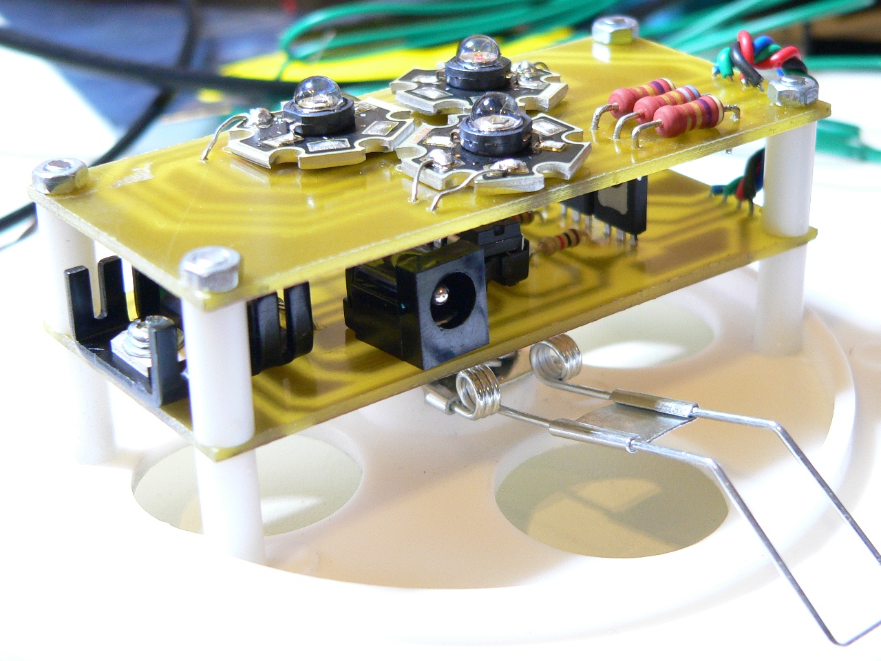
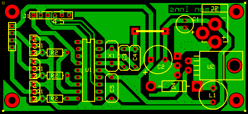
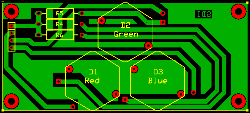
To avoid ‘shadowing’ from the components the circuit board is split in two, the top board contains the LEDs and power-limiting resistors, the bottom board contains the power-regulator (which supplies a steady 5Vs from the 9V input), the computer and 3 power-transistors that act as switches turning the LEDs on and off at the computer’s command.
Circuit Diagram
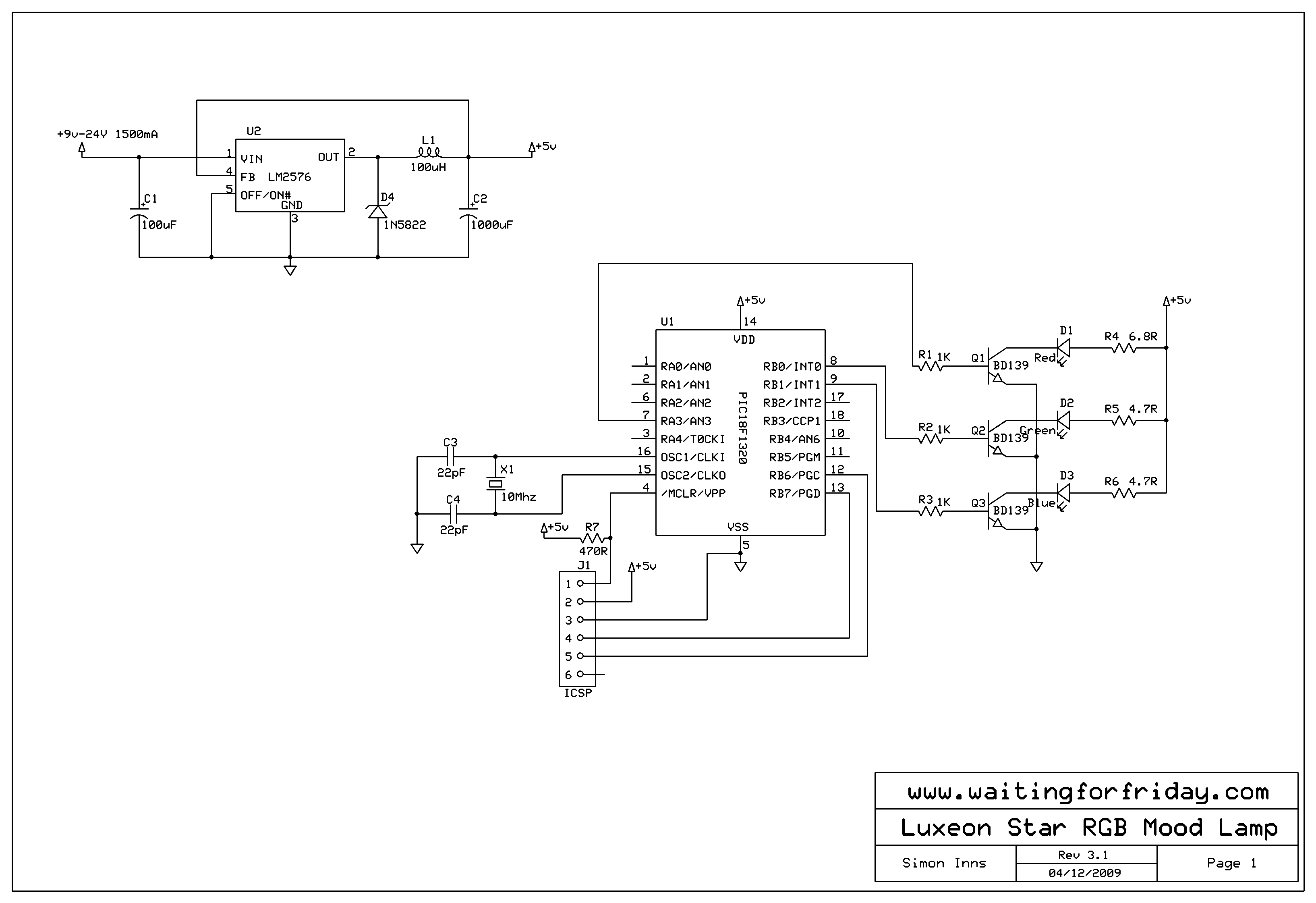
Note: R4, R5 and R6 should be rated for at least 2 Watts.
PCB Artwork
Files for download
Software is covered by GPL, everything else by this site’s Creative Commons licence.
MPLAB Project zip file containing the source code:
ExpressPCB and ExpressSCH files of the PCB and circuit diagram: