Atari Joystick USB Adaptor
Contents
This project implements a composite USB device supporting two USB 2.0 full-speed gameport HID interfaces. The physical joystick ports are wired in accordance to the ‘Atari standard’ allowing connection of most Commodore 64 and Amiga joysticks as well as older Atari 2600 compatible joysticks.
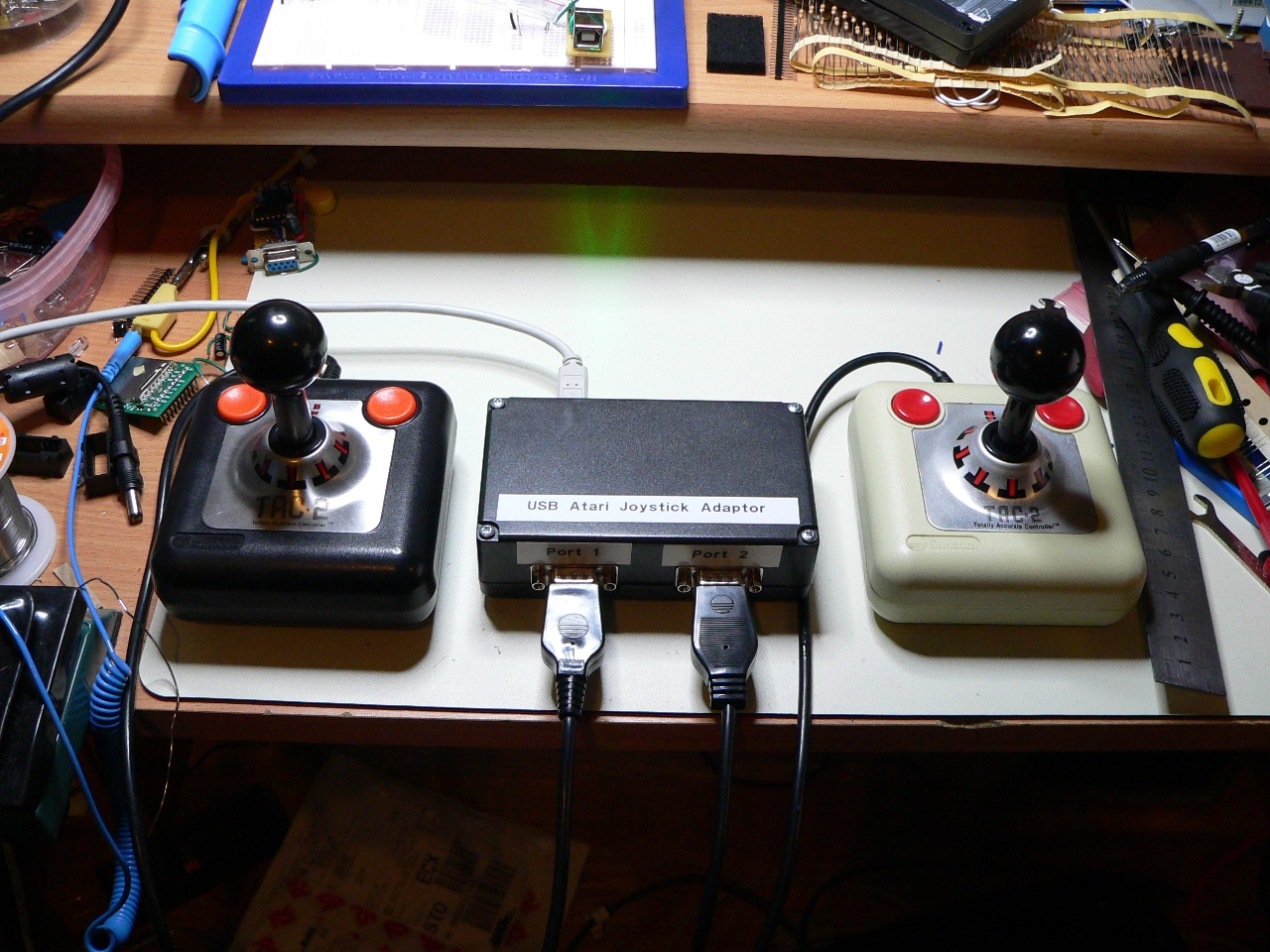
It’s purpose is to allow game play on Linux and Windows emulators (such as VICE) using the original hardware for a more realistic ‘retro’ feel.
I’ve tested the device on both Windows 7 and Ubuntu 9.10, since it is HID-compliant no drivers are necessary, you just plug in and go.
How does it work?
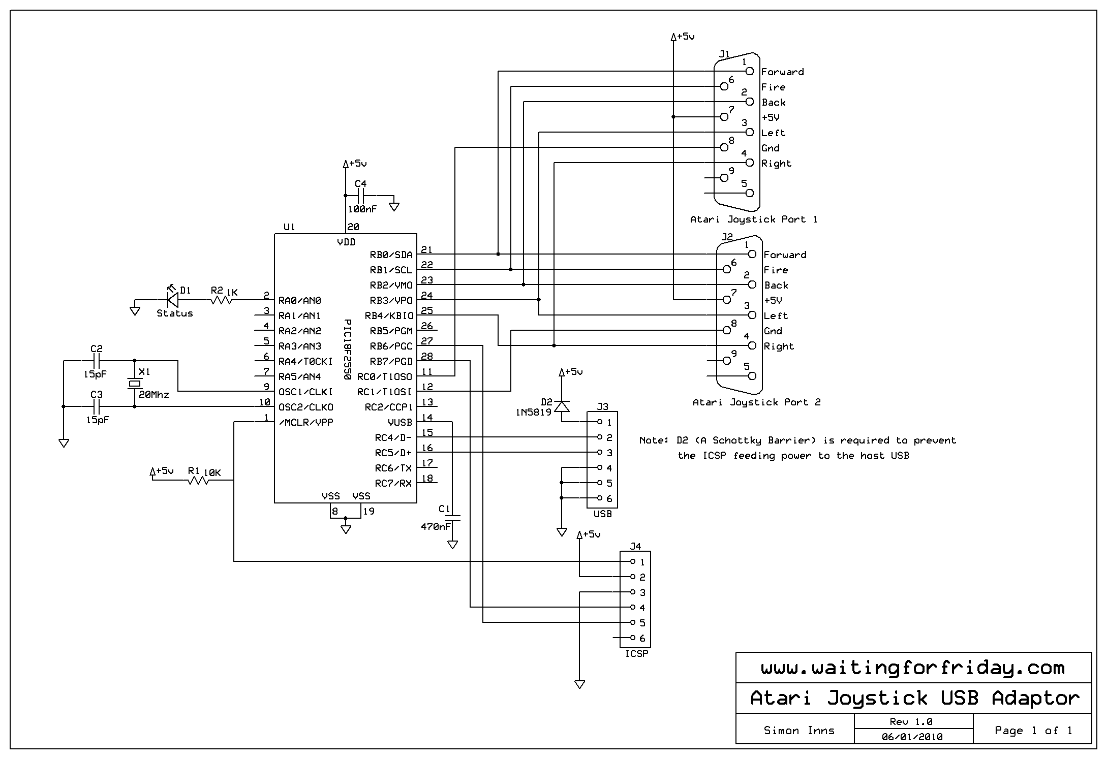
The USB adaptor is built around a PIC18F2550 microcontroller and a port of the Microchip USB stack (to the Hi-Tech C18 PRO compiler). The circuit is designed for minimum component count to allow it to easily be built either on a PCB design (included below) or a small piece of stripboard.
The 2 physical joystick ports are multiplexed onto the PIC’s PORTB, this is to allow use of the PORTB weak pull-up feature on both joysticks (removing the need for 10 pull-up resistors). An optional barrier diode is also included to protect the host computer from power feedback when using an in-circuit programmer. Multiplexing to a single port has the added advantage of leaving PORTA free for future addition of mouse/paddle interfaces (at some point I would like to add an Amiga mouse port to the design).
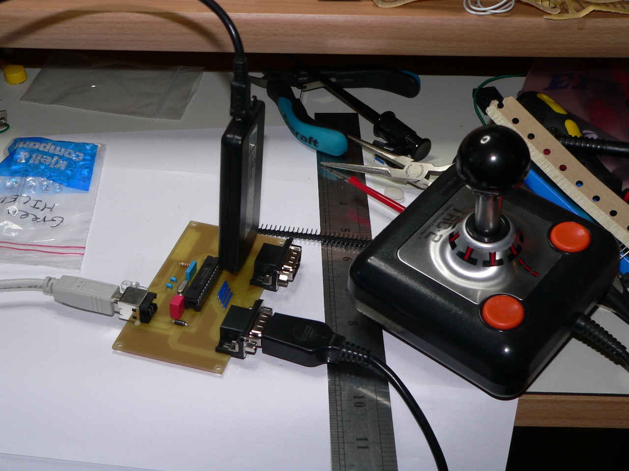
The whole interface consists of 3 ports (2xJoystick, 1xUSB) and 10 components including the PIC. To make it even more compact/cheap you could also remove the status LED (which I included to help debugging) and the MCLR pull-up resistor (required so the ICSP programmer can hold the device in reset – useful when developing).
Most of the complexity is in the software, feel free to download it and adapt it to your purposes. Please note that I don’t have my own USB VID or PID (since it costs $1500!) so you may need to alter the VID and PID in the code if it conflicts with another device (very unlikely since I used the Microchip VID).
The software includes full switch debouncing for both on and off states to ensure you get a good ‘positive’ response from the joystick even if it’s older than your children 🙂
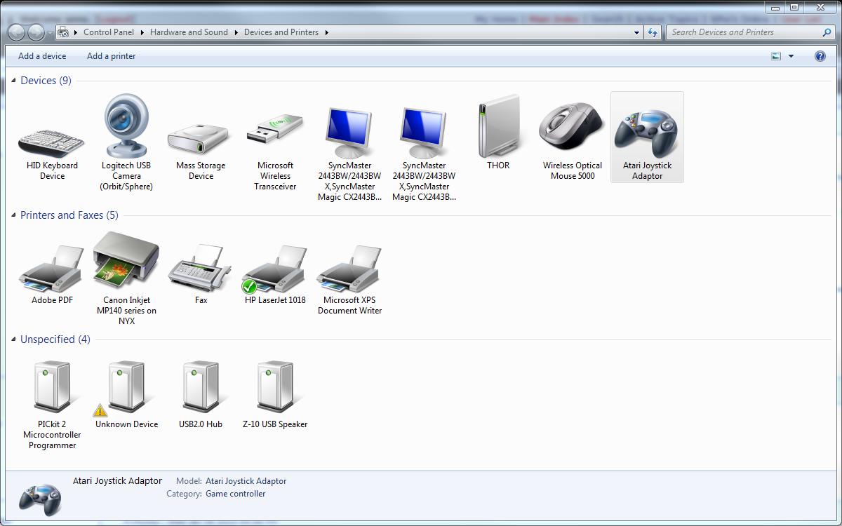
Device USB enumeration
The following picture shows the device loaded in Windows 7 devices and printers panel as ‘Atari Joystick Adaptor’:
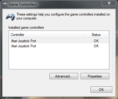
This next picture shows the 2 HID interfaces provided by the composite device:
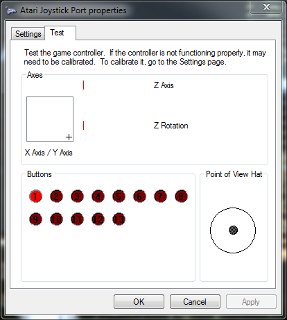
And here is a view of the joystick’s properties in Windows 7 (the joystick is pulled south-east with the fire button held down):
Circuit schematic and PCB artwork
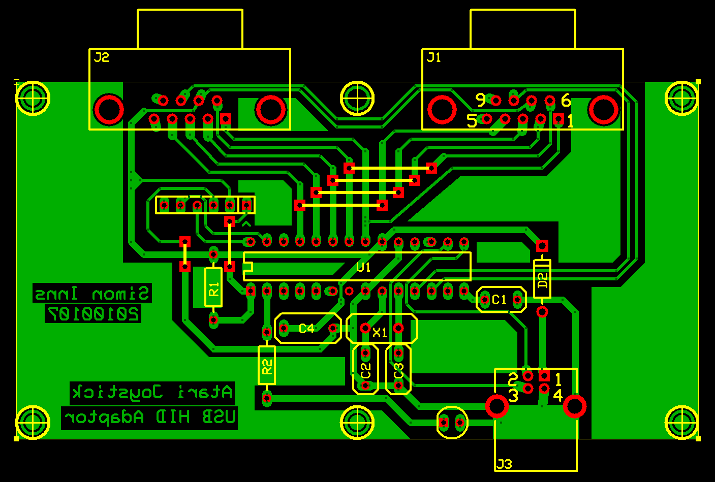
The PCB is designed to fit in a standard half-euro enclosure 120x70x35mm (I’m using one from Kemo, article number G081).
Files for download
Please review this site’s Creative Commons licence before downloading any content.
MPLAB Project zip file containing the source code:
Atari_Joystick_USB_HID_Adaptor
ExpressPCB and ExpressSCH files of the PCB and circuit diagram:
this is great. Thank you very much!