Restoring an Acorn A3000 computer
Contents
Released in 1989, the Acorn BBC A3000 computer was the last of the BBC branded machines Acorn produced and as a ‘cheaper’ all-in-one unit and was the machine most Acorn loving Brits had for games, programming and a whole host of other applications in the early 1990s.
At the time of writing (March 2009) there are still a few of these machines available on Ebay UK and if you don’t already have one, you can easily purchase one for around 50 pounds.
However, now this machine has hit 20 years old, it is not a good idea to just buy one and plug it in… You will probably find that any model you buy has simply been powered on and barely tested. Setting it up and slapping in a floppy to ‘relive old times’ is not going to help the machine live another 20 years or more, you have to do a little restoration.
With a little time and patience you can have the machine back to it’s ‘new’ state and ready for many more years of enjoyment.
In this article I will explain how to get the machine apart, how to restore the case and the machine’s components safely and get it all back together again. If you decided to do nothing else, motherboard battery replacement is the number 1 priority. Nearly every A3000 I have seen recently has been suffering from battery leakage. If left unchecked (like my friend’s A3000 mentioned in my blog) the motherboard, ROM sockets and keyboard connector will be damaged beyond repair… A sad end for a mighty micro.
Do this at your own risk
If you follow these instructions even as carefully as you can you will ALWAYS be at risk of breaking your A3000. Please don’t attempt anything you don’t feel competent enough to do, go find a knowledgeable friend instead. If you do break something either by accident or because there is a mistake in this text I will accept no responsibility for it. You have been warned!
Safety First!
Above all else you must follow some basic safety rules. ALWAYS unplug the machine physically from the mains before placing your hands anywhere near the insides of the machine! The power supply unit in an A3000 is shielded by a thin piece of cardboard with exposed ends directly behind the keyboard. One careless slip and you will receive a nasty (and potentially ”fatal”) shock from the exposed power supply circuitry.
Whilst it is usually unavoidable to run the machine (for testing) without the top-cover, be very careful when you do so and make sure there are no curious small children around (i.e. do not leave the machine powered up and unattended at any time. Also note that simply powering off my the on/off switch is not sufficient. You ”must” physically unplug the machine to be sure.
Static electricity is also very dangerous for these machines, avoid wearing synthetic materials when handling components and, if you can, use an antistatic wrist band which is earthed (clipping it to the unplugged A3000 will not earth it, you will need to clip it to something else which is earthed (such as the case of another PC which is plugged in, etc.)).
Tools you will need
You will need the following tools to do the job properly (you can get by with less, but it increases the risk of damage as you go along):
- A cross-hair screwdriver (i.e. a ‘Phillips’)
- A flat-head screwdriver
- An IC extraction tool (for removing the ROMs)
- A small pair of wire cutters
- A small pair of pliers
- A temperature controlled soldering iron
- A de-soldering tool
- Vacuum cleaner with a small brush attachment
- A small hard brush (a fingernail scrubbing brush is usually perfect)
- A bottle cleaning brush (large and small – as used on baby bottles)
- A small, soft paintbrush (unused!)
- A toothbrush
Note: for the soldering… If you don’t know how to solder, or don’t have the equipment – find someone who does… Replacing the motherboard battery requires this, and is the most important step for the restoration.
If you know a little more about electronics you may also want to use a multimeter which will allow you to test the output from the power supply unit (PSU) to ensure it produces a steady 5V output.
Stripping down the machine for repair and cleaning
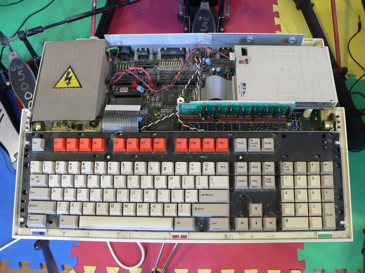
A3000 with the top cover removed (very dirty!)
Opening the case
The A3000’s case is secured by 3 screws and 5 clips. When removing the case use minimal force! You should never have to tug anything or struggle to remove it unless you have made a mistake. If it doesn’t come apart as I describe, go back and check carefully that you have understood the instructions correctly. Here are the steps for case removal:
- Turn the machine upside down and locate the centre screw
- Remove the screw completely with a cross-haired screwdriver
- Turn the machine over with the back facing you
- Locate the two screws on either side of the back panel (they have little metal squares behind them)
- Loosen the screws one by one, do not remove them, only loosen them enough so you can slide them downwards and out of the case without removing them from the metal squares.
- Press down on the two clips (from which you just removed the screws) and gently push the back of the machine’s top cover upwards just enough so the clips spring free of the lower case
- Be very careful not to let the case fall open during the next step – the keyboard is not screwed down inside the case and will fall away from the lower case causing damage to the keyboard membrane connectors if you are careless, try to support the keyboard with your hand as you remove the upper case during the next step
- Turn the machine with the keyboard facing you and then tilt the machine backwards
- Use a flat-headed screwdriver to pop the 3 clips at the front-underneath of the machine (this should require virtually no force), simply insert the screw driver in the gap (which is towards the back of the machine) and turn gently
- Lay the machine down flat and lift the top cover away from the bottom
Removing the keyboard
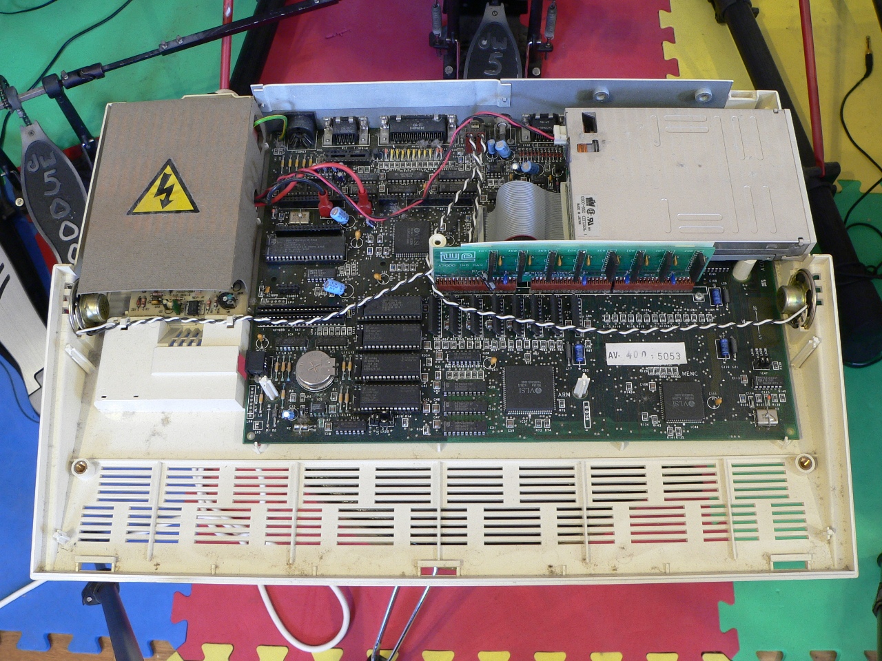
Keyboard removed
The keyboard is connected to the motherboard using two thin membrane ribbon connectors. These are very easy to damage and must be handled with care. Do not reconnect the keyboard until you are sure you have finished with everything else… The conductive material on the connectors is ‘printed on’ and will wear off with repeated removable and insertion.
Note: If you do manage to damage the membrane (or after removal you can see it is already damaged) you can use a conductive silver paint to repair it. You can either buy this from an electronics store, or use rear-window heating strip repair paint available from most automotive stores.
To remove the keyboard remove one membrane connector at a time (starting with the rear-most connector). Simply grip the connect as close to the motherboard as possible with both hands (at either end of the connector) and pull upwards in a single motion. Do not attempt to ‘wiggle’ the connector free, this is likely to cause more friction and therefore more damage to the connector. Simply repeat this for the other connector and then the keyboard should be free of the case and can be removed completely.
Initial clean up of dust
Using your vacuum cleaner (with the brush attachment) remove as much of the dust from the computer and keyboard as you can. Do not ‘scrub’ the components when doing this. Simply bush the vacuum clearer over the keyboard, motherboard and case being careful not to damage or bend any of the small components. If you have an anti-static brush then this is a better alternative (since it lowers the risk of static damage).
Removing the motherboard
Use the following steps to remove the motherboard from the lower-case:
- Firstly unplug and remove the speaker connections from the motherboard. The speakers should then just slide out of the case (store them carefully).
- Now remove the power and floppy cable from the back of the floppy drive. Flip the machine over and remove the four screws holding the drive in place (be careful not to drop the drive whilst doing this). Remove the drive from the machine completely.
- Remove the RAM expansion (if fitted) – this is a long board mounted perpendicular to the motherboard in front of the floppy drive. Simply work it free by pulling gently at the sides of the board until it comes free. Be careful not to bend any pins on the motherboard.
- Mark the order of the four ROMs located next to the battery (if the battery has leaked you will need to clean up the sockets on the motherboard so these chips have to be removed) and then remove them – If you have no intention of repairing the battery, leave them in place. To remove use an IC extraction tool and pull/wiggle the ROMs from the sockets being careful not to bend the pins. Once removed store in anti-static foam for extra protection.
- Now unplug the 0V and 5V power connections from the PSU by simply pulling up the connectors away from the motherboard. You will also need to pull out the earth plug which is on a wire (from the motherboard to the PSU) accessable by a small hole at the back-right of the PSU.
- Now remove the three screws which hold the motherboard in place. One is in the centre of the board, the other is in the back-right corner right at the edge and the final one is centre-right of the board.
- Lift the back of the motherboard slightly, you should now be able to gently push the motherboard back and up to free it from the two clips at the front of the board. Once free of the clips lift the motherboard up and out of the case. Be careful of the PSU cable (at the left of the board) you may need to pull/push the cables out of the way to allow the clearance for the motherboard.
- You can remove the reset switch (on the right of the motherboard) by simply pulling the plastic square off of the physical switch (so it can be cleaned later).
- If you have the correct tool you can remove the nuts around the rear sockets of the motherboard to remove the metal back plate. These metal covers can be washed (see below), however if you don’t have the right tool, I suggest you leave them in place. Don’t remove the back cover until you have replaced the battery though… it makes an excellent stand for the motherboard which prevents you from bending components whilst you remove the battery.
Removing the PSU
To remove the PSU you will need to peel back the yellow sticker (I usually do this carefully so I can replace it afterwards) and unscrew the screw from the PSU board. Note: Some machines do not have a screw, instead there is a small plastic stud which can be removed by using a thin object to push the centre pin downwards in the stud and then you can push the whole stud downwards and out of the bottom of the case.
Lift out the cardboard cover from the right and then remove the earth and mains plugs from the PSU board. You can now remove the PSU board, the cardboard cover and the thin plastic sheet from under the PSU board.
Cleaning the case
With all the components removed you can now clean the case. I suggest using warm (not too hot!) water and a simple detergent like washing up liquid. Usually I fill the bathtub with a couple of inches of water and let the case soak for a while before scrubbing with the nail-brush and bottle brushes to ensure that all of the openings and grills in the case are as clean as possible.
Once you’ve finished, towel dry the components and then leave to drain for a while. Finally use a hair-dryer to remove the rest of the water (especially the water trapped in the grills), but be careful not to make the dryer to hot, or place it too close to the plastic.
You may want to wait until you have opened the keyboard (see below) as then you can wash that at the same time.
The original A3000 only had two rubber ‘feet’ at the back of the case (which have usually fallen off by now). It’s worth buying some self-adhesive rubber feet and replacing them, also putting two more at the front will help keep the computer stable when typing and prevent it from scratching desks when moved.
Cleaning the floppy drive
It is worth removing the top from the floppy drive (simply use a small flat screwdriver and un-clip the 4 metal clips around the top of the case) and then sucking out any dust with a vacuum cleaner. If the dust is left in the drive it will quickly destroy any floppies you put in there later. The heads can also be cleaned using a floppy head cleaner (if you have one) or by using a tape head cleaning fluid and some small lens-cleaning buds. If you don’t know what you are doing I suggest you skip this step (apart from using the vacuum cleaner) as is it is usually unnecessary.
The front plastic panel of the drive can be cleaned fairly easily. I usually use a ‘wet-wipe’ designed for LCD monitors (since it won’t have anything in it that can be damaging to the plastic).
Cleaning the keyboard
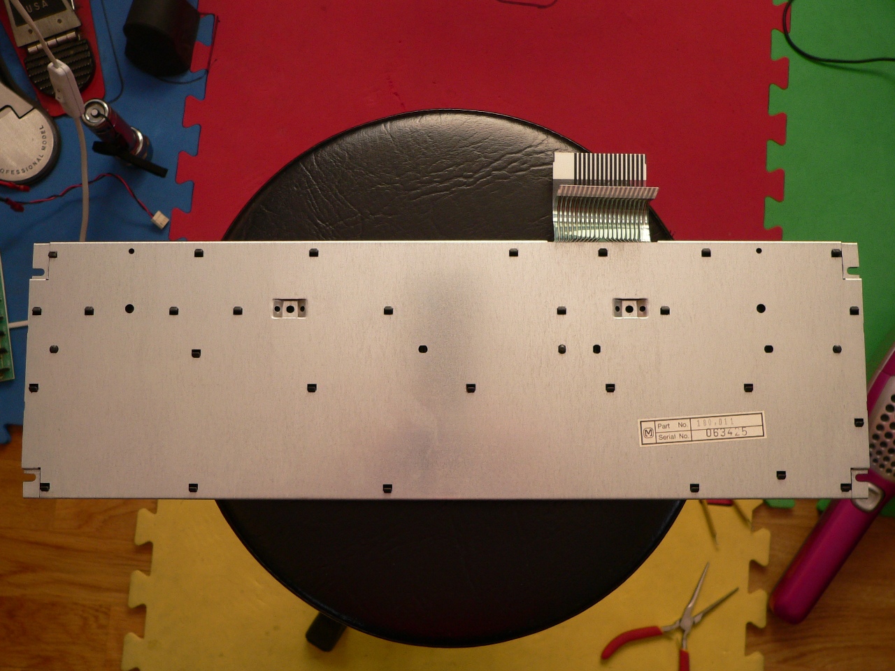
The back of the keyboard
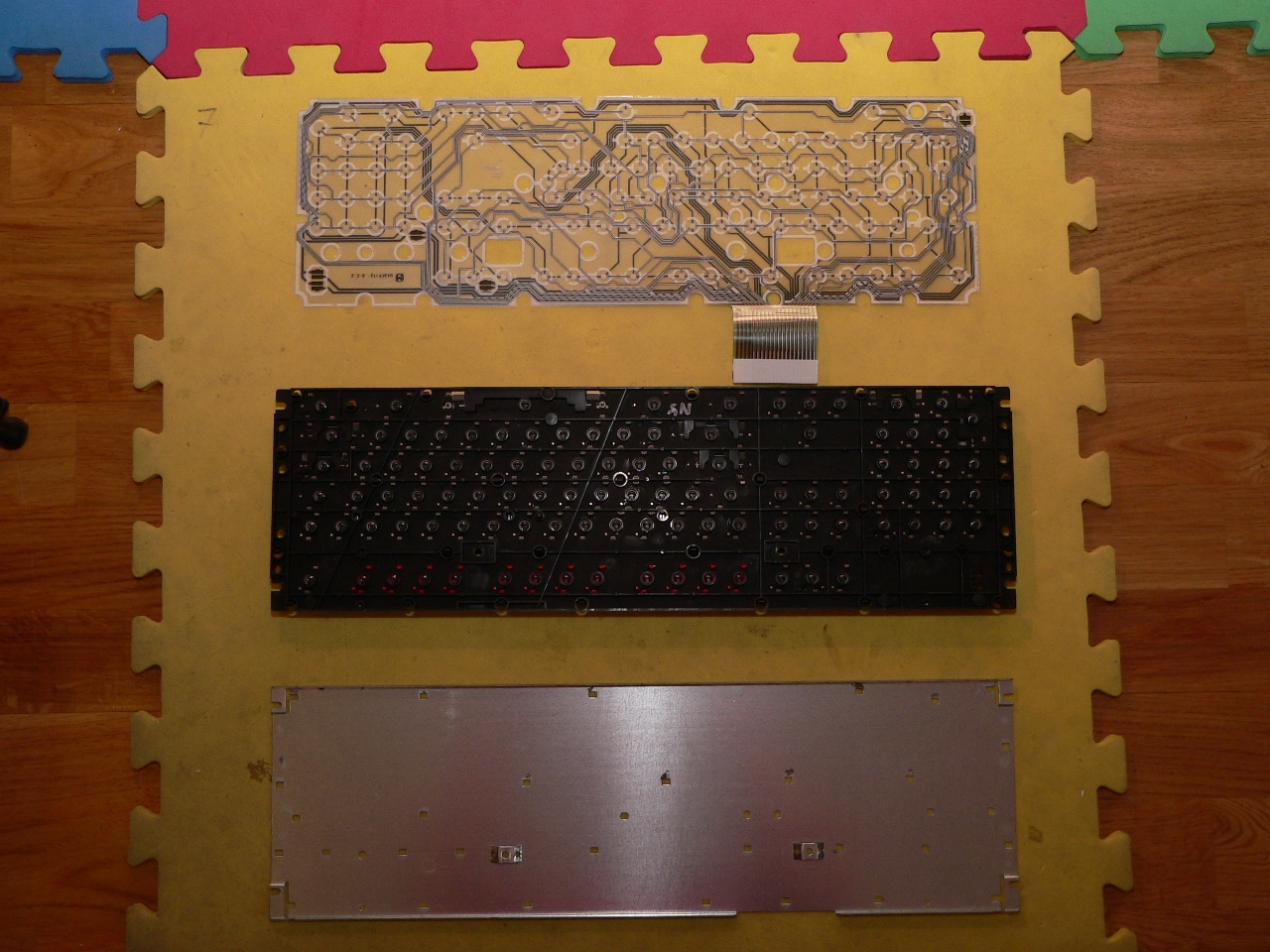
The keyboard parts
The keyboard is made up of a sheet of metal (on the bottom), a plastic layer that supports the keys and two thin membranes which form the switches and the ribbon cable to the motherboard.
The metal plate is held in place by many plastic clips from the top layer. Care must be taken not to bend or break the clips as you disassemble everything. Start with the top of the keyboard and hold the keyboard upright. With your thumb press down on the clips whilst using your fingers to pull the metal sheet back slightly. It will be hard to do the first few clips (they have a tendency to ping back) but after a few are removed the rest come easily. Work your way left-to-right and down the keyboard removing every clip in this manner, once you find the clips are the other way up, simply turn the keyboard over and continue until the metal sheet falls free.
Now lift out the membranes (do not attempt to separate them!) and then lightly vacuum the membrane and the metal plate.
Next remove the LED lights from the back of the plastic key panel. Simply pull them up and store them carefully (there are 5 of them, don’t miss one!) and make sure you remember which one goes where since they are different colours.
Now you can vacuum the dust from the plastic layer, ready for washing in the same manner as the case (described above). For the membrane I would suggest wiping over with a damp cloth and then drying with a glass-towel rather than immersing completely in water (as you don’t want water trapped between the two membranes).
Replacing the motherboard battery
Why do it?
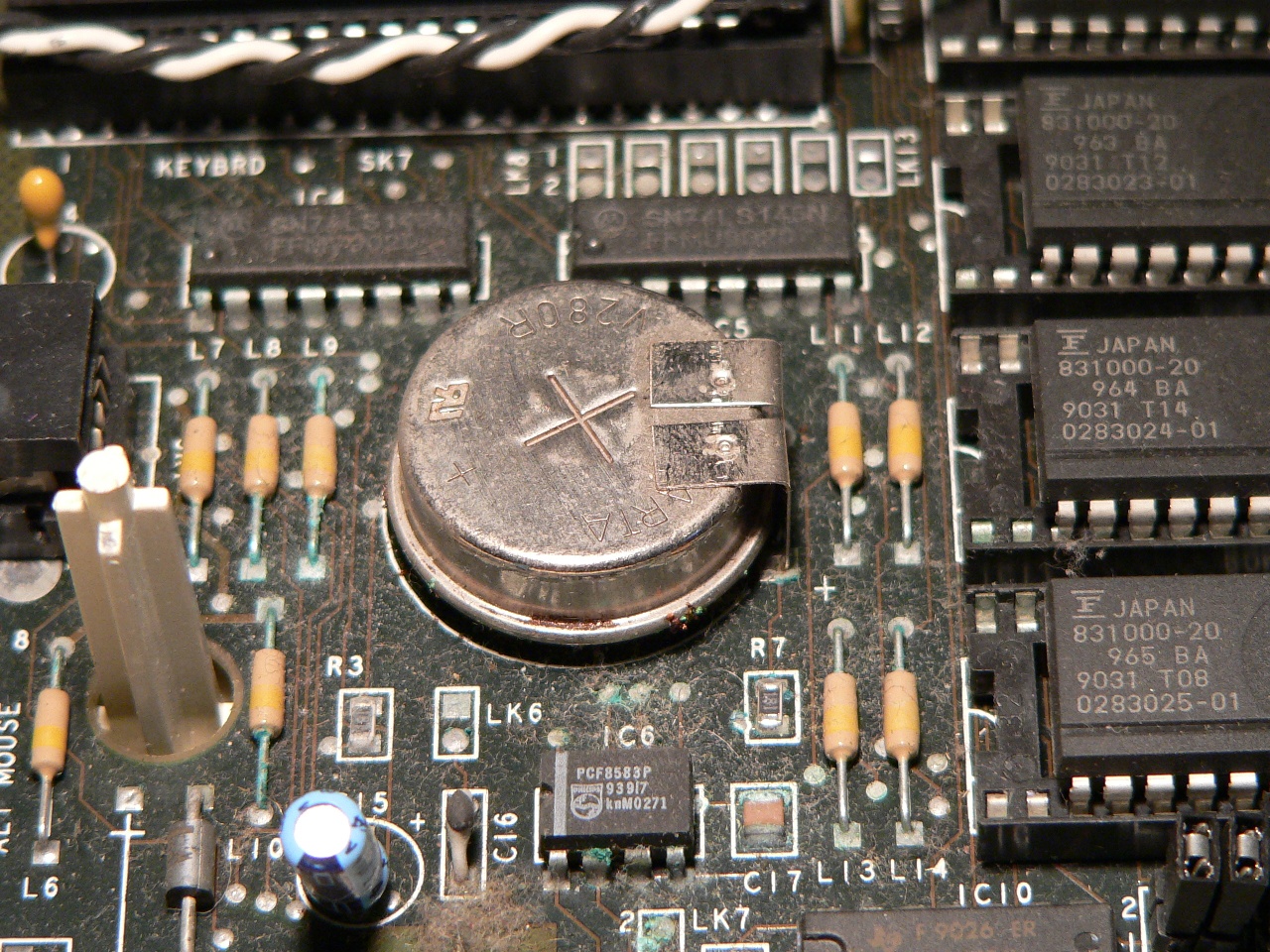
A close-up of the battery and the surrounding damage
In the attached image you can see the battery of the A3000 has leaked (thankfully not very much). Around the battery you will see areas of blue, green corrosion that, if left unchecked, will eventually spell the end of your computer. What you can’t see is underneath the battery where the corrosion is far worse, by the time you see it around the edges of the battery, the underneath is already covered with chemicals. Even if your original battery shows no signs of leaking it is still worth replacing just in case.
Removing the original battery
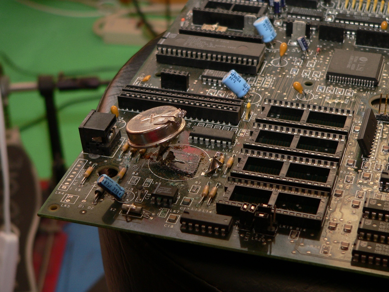
Removing the battery
To prevent damage to the mother board I usually cut the back two connections with a sharp pair of wire-cutters and then lift the battery up and cut the connector underneath the battery allowing me to remove it completely before de-soldering the connections. Then turn the board upside down heat the connection with a soldering iron and use a de-soldering tool to remove as much solder as possible. Only do this once if possible, since heating the motherboard too much is not good. Now (with the motherboard still upside down) grip the connection from underneath with a pair of pliers and gently pull downwards whilst heating the connector. This will pull the remaining connector out of the motherboard with out the risk of lifting the conductive ‘tracks’ on the underneath of the motherboard (something you really really don’t want to happen).
Repeat this for the other two connectors until the original battery is completely gone. At this stage don’t be tempted to scrape the motherboard free of the battery leakage, you risk further damage by doing so. We will clean up the corrosion in the next step. If there is any rubber on the motherboard from underneath the battery, remove it carefully using a blunt instrument like a flat bladed screwdriver (be careful not to scrape the motherboard or bend components as you do this).
Cleaning the motherboard and components
To remove the leakage from the battery you will need to mix up a small amount of vinegar (acetic acid) and water, half and half should be sufficient. The chemicals in the battery are alkaline, so a weak acid is enough to remove an neutralise the chemicals.
Use a toothbrush dipped in the the vinegar/water solution and carefully scrub the affected area, including any component wires and IC sockets that have been affected. Then rinse in a small amount of clean water and leave to dry. You can use a hair dryer (not too hot or too close) to ensure all the water is removed. Get as much of the chemical off as you can, you do not want this stuff sitting on the motherboard’s precious components!
Once you’ve finished with the battery area use the paintbrush and a vacuum cleaner to carefully remove the remaining dust and dirt from the motherboard, after that it should look like new!
Note: one reader pointed out that the airflow from using a vacuum cleaner can generate static electricity which may damage the circuitry and it’s better to wash the board. I usually avoid washing the board since water can get trapped under and around the components (especially IC sockets) and cause damage. However, he makes a valid point, so I’ve included here so you can decide for yourself.
Replacing the battery
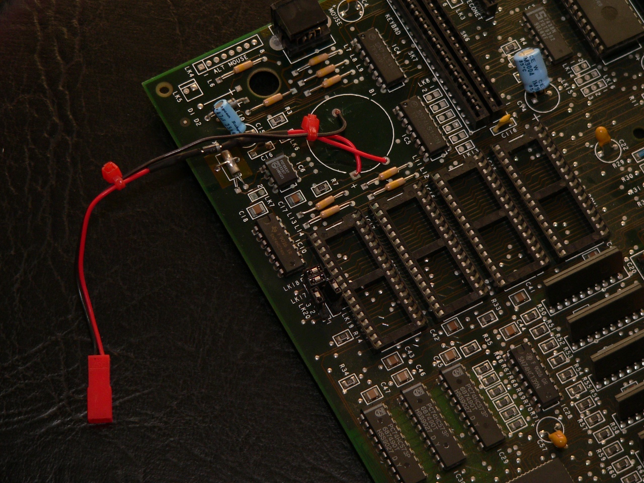
The new battery connector with in-line diode
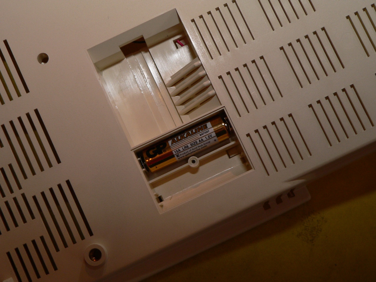
The new battery compartment
The original battery is a Varta V280H which is a single cell 1.2V NiCAD battery. These batteries are long gone and they do not manufacture them any more. The simplest solution is to use a standard 1.5V non-rechargeable battery instead, however this presents two problems, preventing the motherboard from charging the battery and where to mount the battery.
The charging problem is simply solved by placing a diode in between the battery and the motherboard (this is a very small component which only allows electricity to flow in one direction. The second issue is also fairly easy to solve.
For some reason Acorn made a space in the case for 2 1.5V AA cells that was never used in any of the A3000 issues (as far as I know). By grabbing any old device that uses 1.5V batteries (I used an old remote control for a TV I no longer have) you can remove a positive (flat spade) and negative (spring) from the device (simply unsolder it) and then mount it into the A3000 case without modification. You may need to hunt around for something suitable, but it is a very common type of battery connection. This is a great solution since the battery is easily replaced and easily removed if you want to store the computer for any time.
To make it easy to disassemble the A3000 in the future I used a small in-line battery connector and socket which is typically used in remote control cars (and therefore easy to get from your local model shop). The positive wire was cut on the motherboard side of the wire and then a diode is soldered in-line. To the other side of the diode I then soldered two wires (since the motherboard has two positive connections and one negative). Make sure the white band on the diode is on the motherboard side of the cable.
You can see the motherboard cable, diode and plug in the picture (also you can see the result of the cleaning with vinegar to remove the battery leakage).
Reassembly
Refitting the PSU
Firstly replace the power supply unit ensuring that the mains and earth connections at the back are securely fastened. Replace the PSU by wrapping it in the cardboard cover and then putting the whole thing in place left side first and then down with the right side. Make sure the cables are through the hole in the cardboard for the motherboard and that the switch on the left is accessible through the case. Now screw the PSU back in place with the single screw you removed earlier.
Refitting the motherboard
Next reattach the back panel to the motherboard (if you removed it) and slide down the motherboard over the supporting plastic pins in the lower case, be sure to ease the PSU connections over the motherboard as you go. Once it is far enough down ensure that the motherboard is in the two clips at the front of the case before pressing it down into position at the back.
Now screw the motherboard in place using the three screws you removed earlier.
To reattach the power ensure that the earth lead on the back left of the motherboard is firmly connected to the terminal on the PSU. Now connect the black connector to 0V on the motherboard and the red connector to 5V.
Place the two speakers back in to the case and connect the left to the left connector (at the back of the motherboard behind the headphone socket) and the right to the right connector.
Initial testing
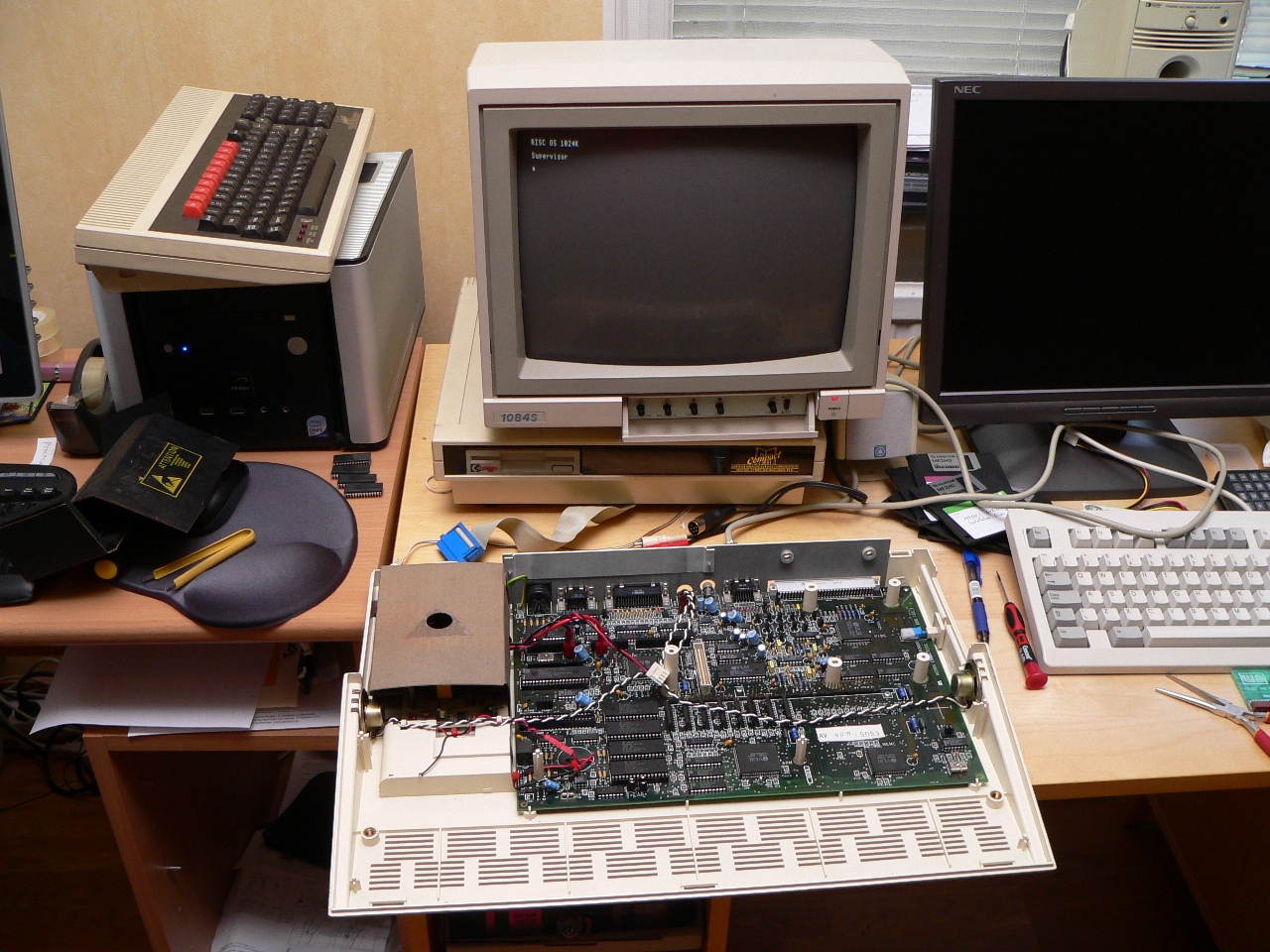
Initial test of the A3000
You are now ready to test the machine (remember about those fragile keyboard connectors? It is best to test now so we don’t have to remove the keyboard again later). Plug in the monitor and the power and switch on the machine at the mains first, then with the switch on the left of the PSU. You should see something like “RISC OS 1024K Supervisor” if you do everything is ok so far. Now turn the machine off again and power it up whilst holding down the Delete key, this will reset the machine to factor defaults (and give you a much more representative test).
If you don’t see the prompt and are getting a completely blank screen first check the power is connected correctly to the motherboard, then that the ROMs are seated properly. Finally ensure that LK18 and LK20 (links) at the front of the motherboard next to the ROMs are correctly set (you will need to check the manual against the type of ROMs you are using).
If you don’t see the prompt, but instead see a rolling white line (or garbled rolling text) check the settings of the video links LK24 and LK25, these control the signal that is sent via the RGB port and are often changed depending on whether the machine is to be used with a composite mono monitor, RGB colour monitor or a SCART cable (this is a very common ‘gotcha’). The links are located just behind the RGB socket and are hard to get at once you have reinstalled the floppy drive.
Hopefully you will now have the supervisor prompt.
Testing the new battery compartment
It is worth checking that your new battery conversion has the diode in the right direction. Testing the voltage in the battery compartment (with the machine powered on) should show a small amount of mVolts if everything is ok (the diode is not 100% efficient). If you see 1.5Vs you have got this round the wrong way. Power off the machine and fix the problem before continuing.
Refitting the floppy drive
To refit the floppy drive (make sure you put the top lid of the floppy drive back after cleaning) simply screw it back in with the four screws you removed earlier. Now connect the power cable from the PSU and refit the floppy cable (the red line goes towards the front of the machine.
Memory expansion cards
If you are lucky enough to have an extra memory card, refit it now before you install the keyboard.
Reassemble and refit the keyboard
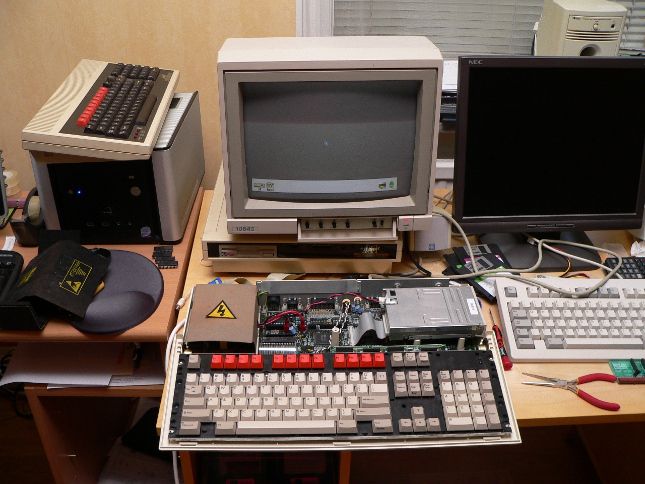
The keyboard is reinstalled in the case
Make sure the whole assembly is completely dry before assembling. Lay the keyboard plastic layer (the bit with the keys attached) face down and then put the 5 LEDs back in place. Now lay over the membranes (they will only fit one way, so check to make sure it looks good before continuing).
Now place the metal layer over the top and start to re-engage the clips moving left to right and top to bottom ensuring all the clips are seated correctly.
Now place the keyboard back into the lower case (there are some plastic locator pins which guide it in). Once the keyboard is in place attach the membrane connector back to the motherboard starting with the one closest to the keyboard. Look to see that the connector is correctly aligned before pressing gently on both sides to push the connector in place (a simple straight push is best, try not to wiggle it into place). Now repeat with the other connector.
Final pre-assembly testing
Now is a good time to fit the battery (you may have to do the Delete-key on boot trick again) and then power up the machine. Once it is running hit F12 and try all the keys and ensure that the 5 LEDs are functioning. You should also see the floppy drive LED light up every time you enter anything and press return.
If the keyboard fails to function check that the membrane connectors are seated properly and if they are you may need to remove them and visually inspect the connections both on the membrane and on the motherboard for any corrosion or damage.
The finished product
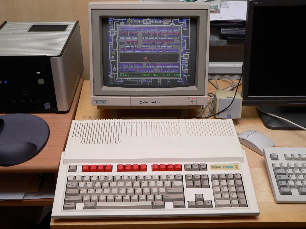
The finished machine
In the image you can see the end result of a careful restoration. A completely brand-new looking A3000 running Bughunter II (great game!). In the pictured machine I also installed RISC OS 3, a Cumana 4Mb memory expansion and an original Conner 59Mb Harddrive and IDE podule.
I’ve ordered a new CF card podule to replace the existing drive (from Ebay), so I hope to install that soon.