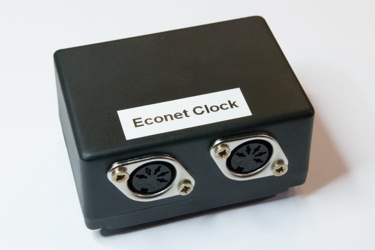
Acorn Econet Clock
Contents
This project creates an Acorn Econet clock suitable for use with Acorn computers from the 1980s and 90s. The Acorn Econet network is an EIA-422-B based network that is driven by a differential clock signal. In the network topology the clock generator is a separate unit that is daisy-chained into the network bus and ensures that all connected Econet ‘stations’ communicate at the same rate.
The Acorn Econet Switch
There are several designs for Econet clocks available on the Internet and even a few commercial providers of clocks, however most designs are based-on (or derived from) Acorn’s original design and require a complex, high-component count circuit in order to operate.
The clock created by this project consists of only 3 primary components (an ATtiny45-20 microcontroller, a capacitor and a resistor) and is therefore much easier to build – in fact, the clock circuit can be quickly built on stripboard saving even the hassle of PCB production. Furthermore, the design is both open-hardware and open-source allowing anyone to duplicate and build the clock (unlike the commercial solutions).
Hardware
Schematic
The schematic for Acorn Econet clock is based on the Atmel ATtiny microcontroller which is a small 8 pin device available in DIP format. Although the microcontroller is clocked from its internal 8MHz oscillator, the PLL and PWM features of the processor are used to clock an internal timer to 64MHz that is more than adequate for producing the 200-400 KHz asymmetric differential clock signal required by Econet.
Previously the Econet clock designs included a differential line driver (such as the defunct SN75159N in the BBC Micro and the AM26LS30 found in later Econet modules). The differential line driver takes a non-inverted clock signal from the clock generator and splits it into the positive (non-inverted) and negative (inverted) signals required for a two-wire differential output. This design takes advantage of the ATtiny45’s PWM output feature that can supply a differential output directly from the OC1B and !OC1B (NOT OC1B) outputs removing the need for an external IC.
Note that the power input to the circuit ”’must”’ be a regulated 5V supply; as the circuit does not contain a regulator. Since the power supply sets the voltage on the clock signals it is very important to ensure the supply does not exceed the TTL levels required by Econet.
The schematic for the clock design is shown below:
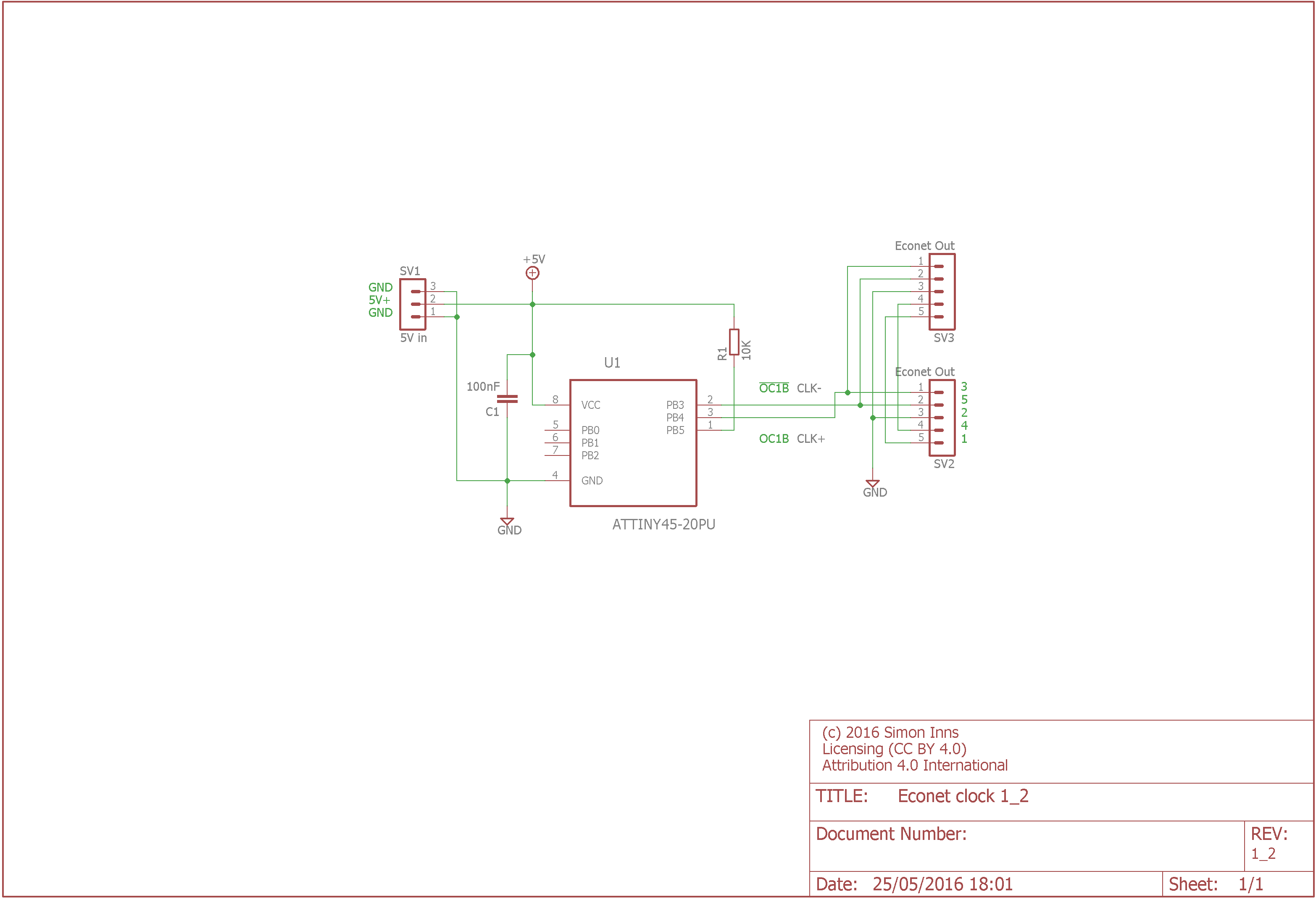
The Acorn Econet Clock Schematic
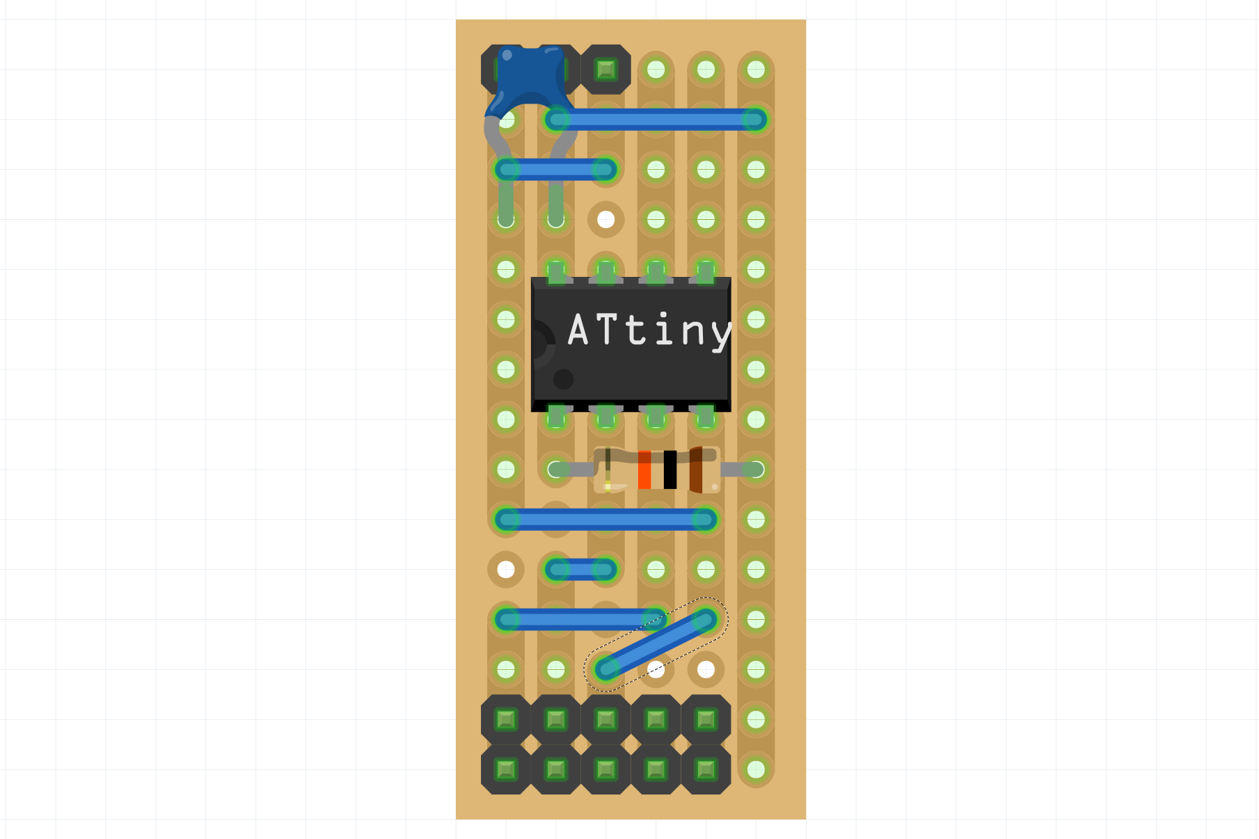
Stripboard Design
In order to make the clock as simple as possible to build the circuit is created on a 6 column by 15 row piece of stripboard. The wiring and component layout is shown in the following picture (created using the fritzing application):
Stripboard layout and wiring
The required components are an ATtiny45-20PU, a 10Kohm 1/4W resistor (5% tolerance) and a 100nF capacitor. Optionally you can choose to add a socket for the ATtiny (so you can remove it and reprogram the clock for different speeds) and header pins to connect the 5-Pin DIN sockets required to connect the clock to the Econet bus and a DC jack for the 5V regulated power supply.
The cut-pattern for the stripboard is shown in the following picture:
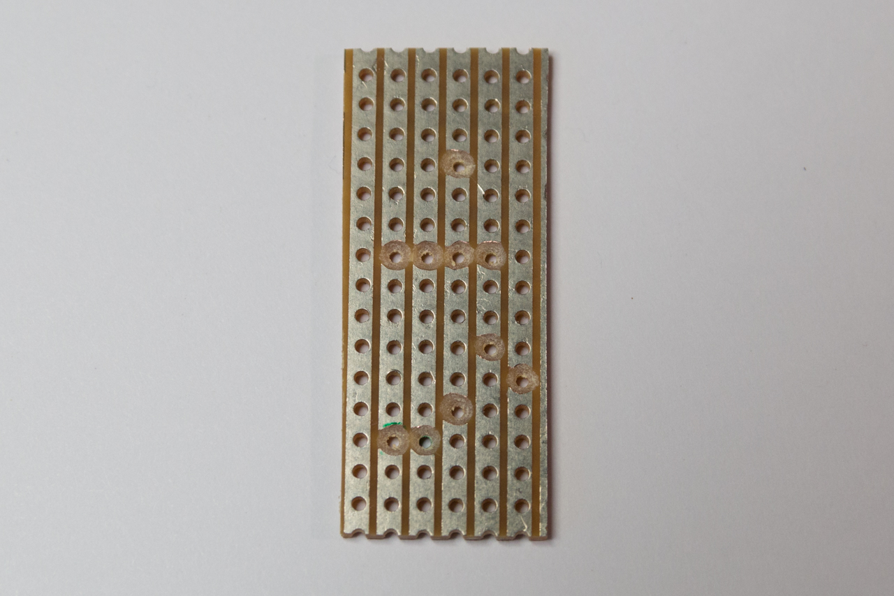
Stripboard cut-pattern
As can be seen from the schematic diagram, the header pin output is in the same order as the pins in the DIN connector. The pin order (from right to left, with the header at the bottom of the board) is 3, 5, 2, 4 and 1. The DIN connector wiring can be easily made and colour coded as shown in the following picture:
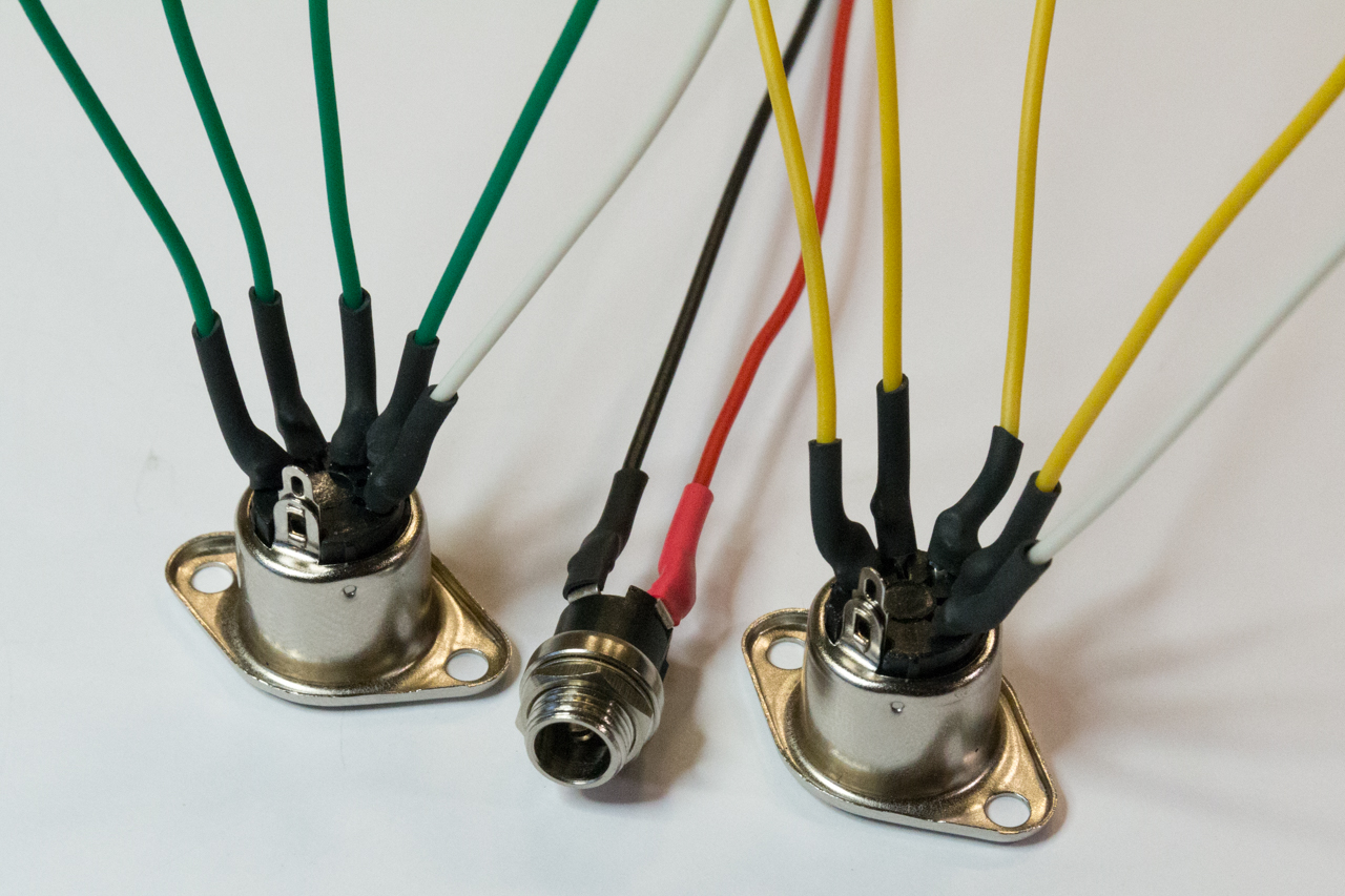
DIN and power connectors
An advantage of both the Econet connector header pin order and the power supply 3-pin header is that reversing the connections (accidentally of course!) will not damage either the clock circuit or any interconnected devices.
If you decide to use pin headers (rather than directly soldering the connectors to the stripboard) then you can use Dupont F connectors to connect the Econet and power jack to the circuit as shown in the following picture:
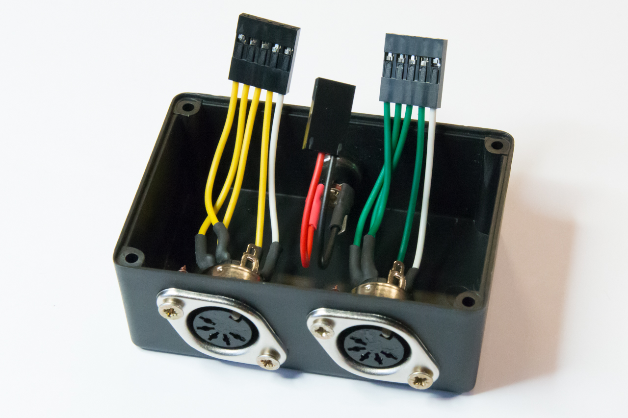
Econet clock case top showing Dupont connectors
Firmware
The firmware project can be downloaded from the bottom of this article and contains a GPL licensed firmware project which can be opened in Atmel Studio 7. The firmware configures the ATtiny Timer/Counter1 to produce the require differential clock signal. The overall frequency of the clock and the length of the mark (the positive pulse) can be freely altered; the source code is heavily commented and contains all the instructions required to make simple modifications to the clock settings. As the ATtiny is clocked by its internal 8MHz oscillator there is some noticeable jitter and inaccuracy in the clock output, but perfectly within tolerance of the required Econet clock signal (and has been tested using both a BBC micro and an Archimedes A440/1). The following picture shows an oscilloscope trace and measurement for the clock with the default settings in the firmware linked below (target clock speed is 250 KHz and the mark period is 0.75 uS):
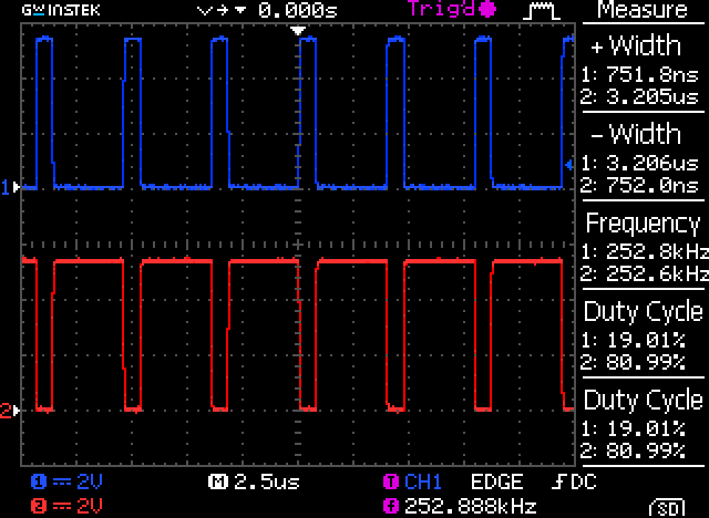
Econet clock output trace
The top channel (channel 1) shows the non-inverted clock output and the bottom channel (channel 2) shows the inverted output.
Please note that the stripboard design does not include a programming header for the ATtiny’s programming pins. The microcontroller will need to be programmed before being inserted into the stripboard. Programming AVR chips is very straight-forward and can even be performed using an Arduino board. There are many good sites on the Internet that cover such subjects, so I shall not repeat the instructions here.
Conclusions
I hope you find this design both useful and flexible. Obviously I haven’t been able to test the clock extensively (since I only have a limited number of retro-Acorn machines) so I welcome your reports of working implementations in the comments.
As the design is open-source and open-hardware I positively encourage you to embrace, modify and even build and sell the design. My intention is to help as many Acorn enthusiasts as possible!
Files for download
This zip file contains the Atmel Studio 7 firmware project files for the project: