PIC18F USART implementation with Go-back-N ARQ
Contents
As part of an ongoing project to build a robot based around the PIC18F range of microcontrollers I decided recently that the flexibility of the robot would be greatly improved with the inclusion of a two-way radio link which interfaced the robot with a computer via USB. To do this I purchase two Easy Radio ER900TRS-02 radio transceivers. However, after some experimentation, it became obvious that the radio link was unreliable and there was a good chance of my precious robot getting confused and disappearing down the stairs uncontrolled…
Therefore, I decided to implement a USART based communication protocol which would (if possible) ensure that the data sent over the USART link was reliably received and, in the case where recovery just is not possible, both the host and the robot would be aware that the link has failed (and can therefore do something sensible like turning off the servos).
Since this implementation is useful for a range of projects I decided to implement it as a library which can be used for projects which require reliable, monitored data transfer over links which have a fairly high latency (such as radio-based links).
The USART Demonstration Board
In order to develop a complicated communication system you need to have a good, stable hardware reference design from which to work from. Since the protocol needs to deal with both Rx and Tx channel corruption as well as near-end and far-end resets (one or the other end ‘disappearing’) the reference hardware must allow you to create data-link failures on demand.
For this purpose I designed the following schematic:
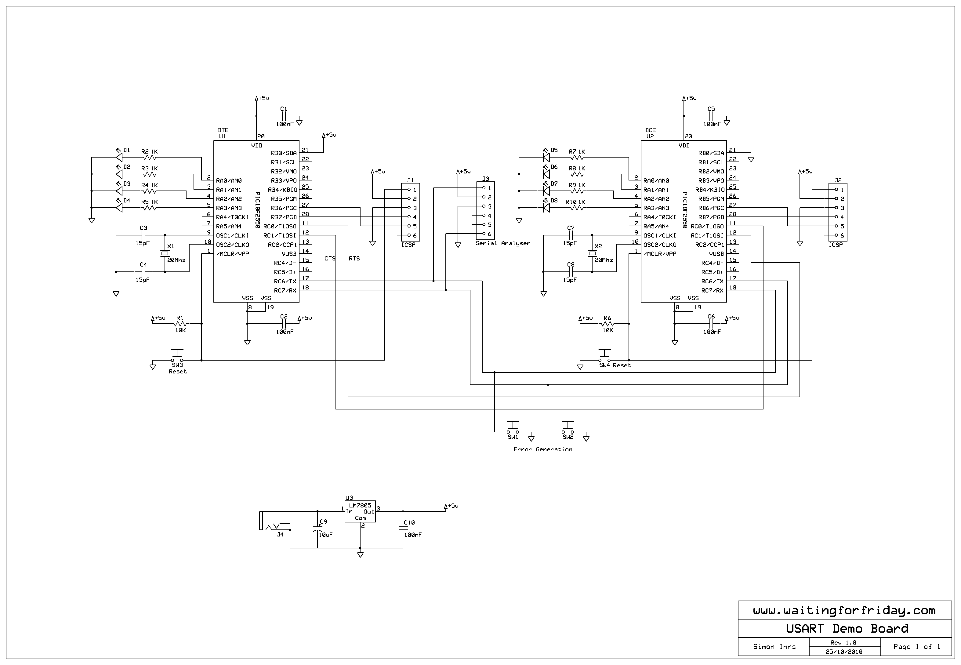
As can be seen in the schematic the hardware consists of two PIC18F2550 microcontrollers connected together via the USART Tx and Rx lines (in a DTE to DCE configuration). Both processors have 20Mhz oscillators to allow them to run at the full 48Mhz speed. In addition both chips can be easily reset using push-buttons. There are a further 2 push-buttons connected between the Tx and Rx lines, both switches are then connected to earth. This means that, if you press one of the buttons, either the Tx or Rx line will stop functioning simulating a drop in the communication channels.
Each PIC has 4 LEDs which are used to show the status of the data-link (up or down), the 2 remaining LEDs show the data traffic flow between the chips to make it easy to see if the firmware is functioning correctly.
The hardware also has 2 programming headers to allow rapid development. In addition there is an extra header for the Microchip PICkit serial analyser which allows you to use the analyser in place of the DTE processor (I didn’t use this function in this project, but thought that it might be useful in the future for other work).
One of the big issues with designing, coding and testing protocol stacks is that you have at least two sides to program. For the demo board I wanted to be able to program both PICs with the same firmware. To enable this I used RB0 on both PICs to indicate if the PIC was the DTE or DCE. RB0 is +5 volts on the DTE and 0 volts on the DCE. This allows an easy test in the firmware to determine the flow of the stack whenever necessary.
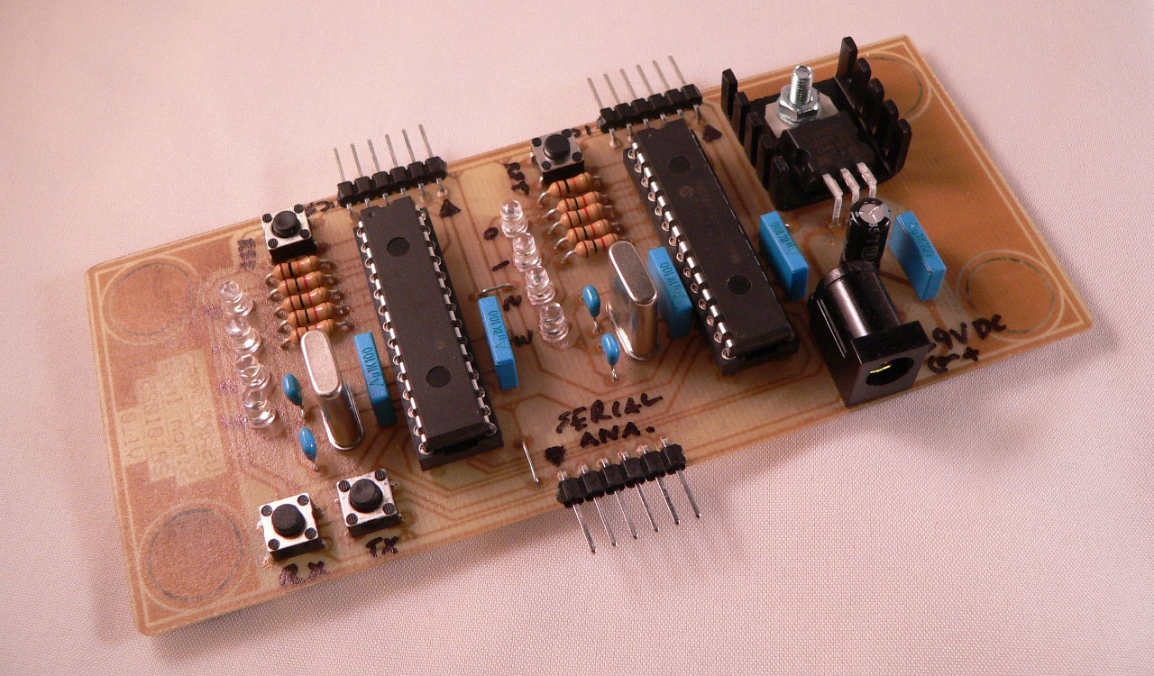
The schematic was then produced on a simple one-sided PCB complete with power regulation and a standard DC jack as shown in the following PCB design:
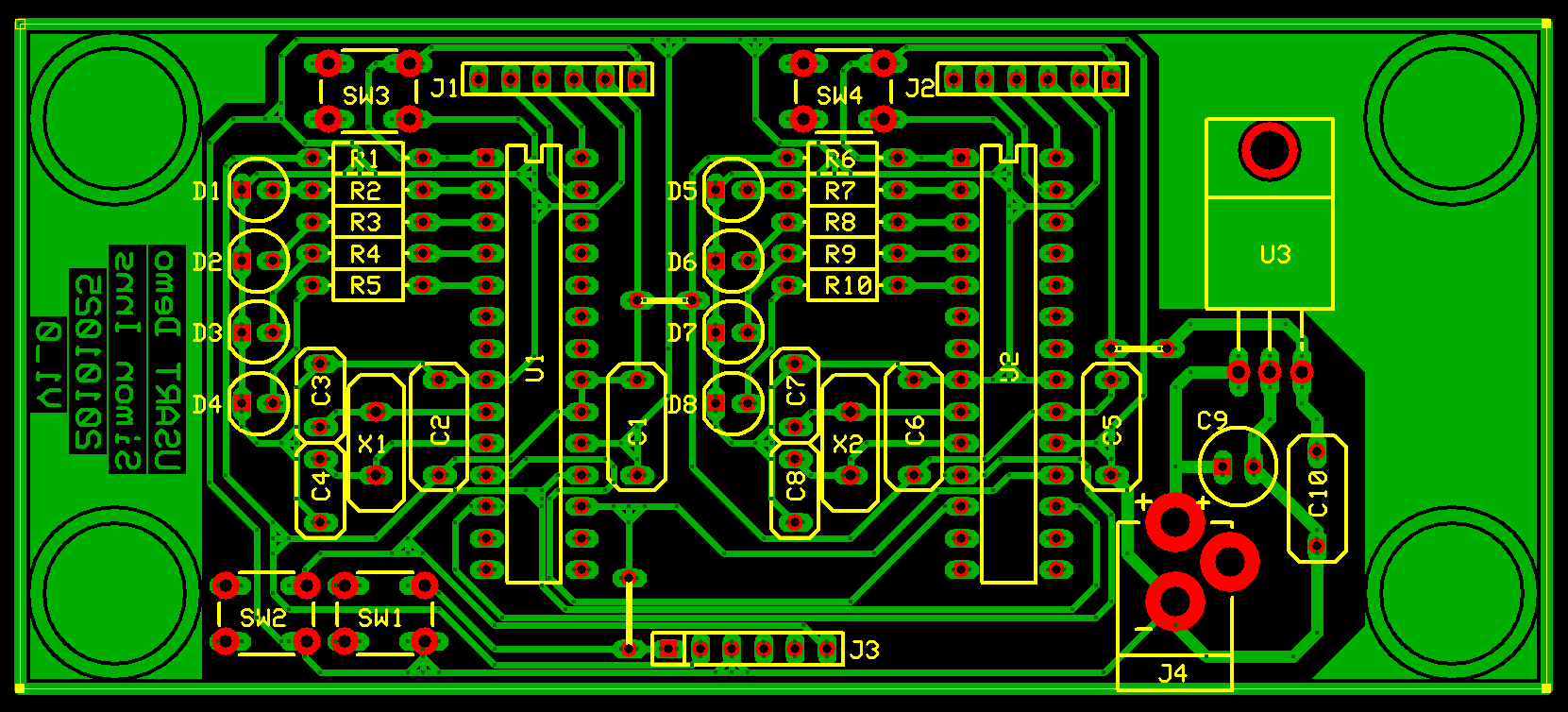
As can be seen above, the PCB also includes space for some rubber feet to stop the board sliding around as you attach and detach the PIC programmer.
YouTube Demonstration Video
Firmware Design
For this style of communication there are basically 3 choices of how to implement the protocol (and many variations of the 3):
- Stop-and-wait ARQ – This is where the sender transmits a frame and then waits for the receiver to acknowledge it
- Go-back-N ARQ – This is a sliding window protocol where the sender transmits a ‘window’ of frames before requiring an acknowledgement
- Selective repeat ARQ – This is a more advanced version of Go-back-N where the receiver can request a particular frame to be re-transmitted.
For links which have noticeable latency Stop-and-wait ARQ (Automatic Repeat reQuest) is not preferable as the utilisation of the available bandwidth is very low, since the transmitter spends most of its time waiting rather than transmitting. So the obvious choice is either Selective repeat ARQ or Go-back-N. I chose Go-back-N because selective repeat requires buffers on both sides of the communication (since frames can arrive out of order). Since the PIC18F2550 only has 2K of RAM (of which only 1K is available if the USB module is on) buffer space is at a premium.
The Go-back-N only requires a frame buffer on the transmitting side so represents the best compromise of link utilisation and RAM use. You can find a good explanation of the 3 different types of ARQ on [http://en.wikipedia.org/wiki/Automatic_repeat-request Wikipedia] if you are interested in the theory behind how they work.
The firmware is split into the physical layer (which deals with sending bytes over the physical interconnection) and the data-link layer (which deals with link monitoring, error correction and flow-control).
Physical Layer Firmware
The physical layer is responsible for sending and receiving bytes to and from the USART hardware. It is not concerned with the reliability of the transferred data, but it is obviously preferable that the physical layer is as reliable and efficient as possible.
Tx and Rx buffer interaction
The firmware implements two cyclic buffers which buffer both the data to be transmitted and the data which is received. Since the layer has no control over when data is received this has to be as ‘real-time’ as possible to prevent data loss, therefore the Rx buffer is typically bigger than the Tx buffer. The firmware implements two functions which write data to the Tx buffer and reads data from the Rx buffer:
// Read a byte from the Rx cyclic buffer
unsigned char readByteFromRxBuffer(void)
{
	unsigned char readByte = 0;

	if (rxBufferLevel != 0)
	{
		// Disable the rx interrupt
		RCIE = 0;

		readByte = rxBuffer[rxBufferStart];
		rxBufferStart = (rxBufferStart + 1) % RXBUFFERSIZE;

		// Decrement the buffer level indicator
		rxBufferLevel--;

		// Enable the rx interrupt
		RCIE = 1;
	}

	return readByte;
}

// Write a byte to the Tx cyclic buffer
void writeByteToTxBuffer(unsigned char byteToWrite)
{
	// Wait until we have space (the transmission interrupt will clear this
	// condition quickly)
	while (txBufferLevel == TXBUFFERSIZE);

	// Disable the tx interrupt
	TMR0IE = 0;

	// Buffer is not full, write the byte and update the end pointer
	txBuffer[txBufferEnd] = byteToWrite;
	txBufferEnd = (txBufferEnd + 1) % TXBUFFERSIZE;

	// Increment the buffer level indicator
	txBufferLevel++;

	// Enable the tx interrupt
	TMR0IE = 1;
}
The buffer pointers are incremented using a simple modulus (%) operation which causes the counter to ‘wrap’ back through zero once the maximum buffer size is reached. With this style of cyclic buffer implementation the start and end pointers are equal when the buffer is either completely empty or totally full. Therefore a buffer level variable is kept in order to track the status of the buffer.
Tx and Rx interrupts
To send and receive the data 2 interrupts are used; one is a high-priority interrupt which deals with filling the Rx buffer with received data and the other is a low-priority interrupt which deals with sending the data stored in the Tx buffer. The Rx interrupt is triggered by the RCIF interrupt condition (indicating that a byte is waiting) and the Tx interrupt is time-based (and is called 20 times a second). The Tx interrupt is also used to update an ACK timer which is used by the data-layer to time-out ACK frames (it is included in the physical layer for coding convenience, but really belongs in the upper level).
Here is the code for the interrupt handling routines:
// Low priority interrupts
void interrupt low_priority lpHandler(void)
{
	// Is Timer0 interrupting (USART Tx interrupt timer)
	if (TMR0IF)
	{
		// Do we have data waiting?
		while (txBufferLevel != 0)
		{
			// Wait until the PIC USART TX is not busy
			while(!TRMT);

			// Send the next byte
			TXREG = txBuffer[txBufferStart];

			#ifdef TESTMODE
				plTxCounter++;
			#endif

			// Update the cyclic buffer pointer
			txBufferStart = (txBufferStart + 1) % TXBUFFERSIZE;

			// Decrement the buffer level indicator
			txBufferLevel--;
		}

		// Update the ACK timer
		if (ackTimerStatus == TRUE) ackTimer++;
		if (ackTimer == 255) ackTimer = 0;

		// Reset the timer0 counter
		TMR0L = 0xC1;
		TMR0H = 0xB6;

		// Clear the timer0 interrupt flag
		TMR0IF = 0;
	}
}

// High priority interrupts
void interrupt hpHandler(void)
{
	// USART Receive interrupt?
	if (RCIF)
	{
		// Check for overrun error condition
		if (OERR == 1)
		{
			// Clear the overrun error condition
			CREN = 0;
			CREN = 1;

			#ifdef TESTMODE
				plORCounter++;
			#endif
		}
		else
		{
			if (rxBufferLevel != RXBUFFERSIZE)
			{
				// Buffer is not full, write the byte and update
				// the end pointer
				rxBuffer[rxBufferEnd] = RCREG;
				rxBufferEnd = (rxBufferEnd + 1) % RXBUFFERSIZE;

				#ifdef TESTMODE
					plRxCounter++;
				#endif

				// Increment the buffer level indicator
				rxBufferLevel++;
			}
			else
			{
				// Throw the waiting byte away
				unsigned char throwAwayByte = RCREG;

				#ifdef TESTMODE
					plRxThrowCounter++;
				#endif
			}
		}

		// RCIF is cleared when RCREG is read
	}
}
As can be seen above, if an overrun condition occurs (another byte is received before the current one was read) the condition is automatically cleared (but at least one byte is lost). Also if the Rx cyclic buffer overflows, the firmware simply discards bytes until there is room again. The physical layer also provides a reset function which clears the Tx and Rx buffers.
When reading or writing the buffers the Tx and Rx interrupts are temporarily disabled. This prevents the possibility of two simultaneous updates to the buffers.
The optimum size of the Tx and Rx buffers is dependent on the available RAM as well as the amount of data expected from the upper layer (especially around how ‘bursty’ the data will be. Due to the ‘bursty’ nature of a go-back-N ARQ algorithm the receive buffer should be around the same size as the overall transmission window. For example, if the packet payload size is 32 bytes and the overhead is 7 bytes with a window size of 3, the buffer should be (32+7) * 3 = 117 bytes minimum to a maximum of (64+7) * 3 = 213 bytes if you expect a lot of byte stuffing in the frames (byte stuffing is covered in the data-link section below). The Tx buffer is less of a problem. The lower it is the more the stack will have to wait causing less utilisation of the available BPS (bits per second) from the USART.
Data-link Layer Firmware
The data-link layer is where most of the complexity of the implementation resides. The major functions of the data-link layer are included below with explanations of what they do.
CRC16 Checksums
In order to provide error checking a simple CRC16 routine is implemented which creates a 16-bit checksum for the data which is passed to it. This is implemented using a table of values (which simplifies the routine greatly). Since this table can be stored in the PIC’s program memory it also has no impact on the available RAM space:
// CRC 16 Look-up table (stored in program memory)
const unsigned int crcTable[0x100] =
{
 0x0000, 0x1021, 0x2042, 0x3063, 0x4084, 0x50A5, 0x60C6, 0x70E7,
 0x8108, 0x9129, 0xA14A, 0xB16B, 0xC18C, 0xD1AD, 0xE1CE, 0xF1EF,
 0x1231, 0x0210, 0x3273, 0x2252, 0x52B5, 0x4294, 0x72F7, 0x62D6,
 0x9339, 0x8318, 0xB37B, 0xA35A, 0xD3BD, 0xC39C, 0xF3FF, 0xE3DE,
 0x2462, 0x3443, 0x0420, 0x1401, 0x64E6, 0x74C7, 0x44A4, 0x5485,
 0xA56A, 0xB54B, 0x8528, 0x9509, 0xE5EE, 0xF5CF, 0xC5AC, 0xD58D,
 0x3653, 0x2672, 0x1611, 0x0630, 0x76D7, 0x66F6, 0x5695, 0x46B4,
 0xB75B, 0xA77A, 0x9719, 0x8738, 0xF7DF, 0xE7FE, 0xD79D, 0xC7BC,
 0x48C4, 0x58E5, 0x6886, 0x78A7, 0x0840, 0x1861, 0x2802, 0x3823,
 0xC9CC, 0xD9ED, 0xE98E, 0xF9AF, 0x8948, 0x9969, 0xA90A, 0xB92B,
 0x5AF5, 0x4AD4, 0x7AB7, 0x6A96, 0x1A71, 0x0A50, 0x3A33, 0x2A12,
 0xDBFD, 0xCBDC, 0xFBBF, 0xEB9E, 0x9B79, 0x8B58, 0xBB3B, 0xAB1A,
 0x6CA6, 0x7C87, 0x4CE4, 0x5CC5, 0x2C22, 0x3C03, 0x0C60, 0x1C41,
 0xEDAE, 0xFD8F, 0xCDEC, 0xDDCD, 0xAD2A, 0xBD0B, 0x8D68, 0x9D49,
 0x7E97, 0x6EB6, 0x5ED5, 0x4EF4, 0x3E13, 0x2E32, 0x1E51, 0x0E70,
 0xFF9F, 0xEFBE, 0xDFDD, 0xCFFC, 0xBF1B, 0xAF3A, 0x9F59, 0x8F78,
 0x9188, 0x81A9, 0xB1CA, 0xA1EB, 0xD10C, 0xC12D, 0xF14E, 0xE16F,
 0x1080, 0x00A1, 0x30C2, 0x20E3, 0x5004, 0x4025, 0x7046, 0x6067,
 0x83B9, 0x9398, 0xA3FB, 0xB3DA, 0xC33D, 0xD31C, 0xE37F, 0xF35E,
 0x02B1, 0x1290, 0x22F3, 0x32D2, 0x4235, 0x5214, 0x6277, 0x7256,
 0xB5EA, 0xA5CB, 0x95A8, 0x8589, 0xF56E, 0xE54F, 0xD52C, 0xC50D,
 0x34E2, 0x24C3, 0x14A0, 0x0481, 0x7466, 0x6447, 0x5424, 0x4405,
 0xA7DB, 0xB7FA, 0x8799, 0x97B8, 0xE75F, 0xF77E, 0xC71D, 0xD73C,
 0x26D3, 0x36F2, 0x0691, 0x16B0, 0x6657, 0x7676, 0x4615, 0x5634,
 0xD94C, 0xC96D, 0xF90E, 0xE92F, 0x99C8, 0x89E9, 0xB98A, 0xA9AB,
 0x5844, 0x4865, 0x7806, 0x6827, 0x18C0, 0x08E1, 0x3882, 0x28A3,
 0xCB7D, 0xDB5C, 0xEB3F, 0xFB1E, 0x8BF9, 0x9BD8, 0xABBB, 0xBB9A,
 0x4A75, 0x5A54, 0x6A37, 0x7A16, 0x0AF1, 0x1AD0, 0x2AB3, 0x3A92,
 0xFD2E, 0xED0F, 0xDD6C, 0xCD4D, 0xBDAA, 0xAD8B, 0x9DE8, 0x8DC9,
 0x7C26, 0x6C07, 0x5C64, 0x4C45, 0x3CA2, 0x2C83, 0x1CE0, 0x0CC1,
 0xEF1F, 0xFF3E, 0xCF5D, 0xDF7C, 0xAF9B, 0xBFBA, 0x8FD9, 0x9FF8,
 0x6E17, 0x7E36, 0x4E55, 0x5E74, 0x2E93, 0x3EB2, 0x0ED1, 0x1EF0
};

// Create CRC16 value for 'dataLength' bytes in 'data'
unsigned int createCRC16(unsigned char *data, unsigned char dataLength)
{
	unsigned int accumulator;

	// Pre-conditioning
	accumulator = 0xFFFF;

	for (unsigned char counter = 0; counter < dataLength; counter++)
	{
		accumulator = ((accumulator & 0x00FF) << 8) ^ crcTable[((accumulator >> 8) ^ *data ++ ) & 0x00FF];
	}

	return(accumulator);
}
Frame structure
The data-link layer implements a simple frame structure for sending and receiving data which is used for command, data and acknowledgement frames:
- Start Flag (0x7E)
- Header – Frame number (1 byte), frame type (1 byte) and number of bytes in the payload (1 byte)
- Data from upper layer (0 to 32 bytes (stuffed to 0 to 64 bytes))
- Trailer – CRC16 checksum of data (2 bytes; high-byte and low-byte)
- End Flag (0x7E)
Transmitting frames
There are two functions in the data-layer for transmitting frames. The first is only used for ACK packets (which do not have to be buffered), it simply creates and transmits the ACK packet on-the-fly reducing the need for temporary buffer space. The data payload of an ACK frame is always 1 byte which is used to communicate the current data-link status to the far-end (which is used during link establishment):
// Create an ACK frame
void sendACKFrame(unsigned char sequenceNumber, unsigned char dataLinkStatus)
{
	LED1 = 1;
	unsigned char ackFrame[5];

	// Store the header values in the transmission frame buffer
	writeByteToTxBuffer(FLAG); 		// Send the flag
	writeByteToTxBuffer(sequenceNumber);	// Send the frame number
	writeByteToTxBuffer(ACK_FRAME);		// Send the frame type
	writeByteToTxBuffer(1);			// Send the data payload length
	writeByteToTxBuffer(dataLinkStatus);	// Send the data link status

	// Create a checksum for the header and pay load data
	ackFrame[0] = FLAG;
	ackFrame[1] = sequenceNumber;
	ackFrame[2] = ACK_FRAME;
	ackFrame[3] = 1;
	ackFrame[4] = dataLinkStatus;

	unsigned int checksum = createCRC16(ackFrame, 5);

	// Split the checksum into two bytes
	unsigned char checksumHighByte = (unsigned char)((checksum & 0xFF00) >> 8);
	unsigned char checksumLowByte = (unsigned char)(checksum & 0x00FF);

	// Store the footer
	writeByteToTxBuffer(checksumHighByte);	// Send the checksum (high byte)
	writeByteToTxBuffer(checksumLowByte);	// Send the checksum (low byte)
	writeByteToTxBuffer(FLAG);	 	// Send the flag
	LED1 = 0;

	#ifdef TESTMODE
		dlAckSent++;
	#endif
}
The second function is used to transmit data and command frames. This function assembles the frame directly into the ‘window’ buffer which stores the frames which are currently waiting for ACK from the far-end. The first thing the function does is to find a free ‘slot’ for the frame within the window buffer, then it copies the required data directly into the frame buffer selected. Finally it creates a checksum for the header bytes and the data payload and inserts it into the frame’s footer:
// Create a frame with a maximum of 32 bytes of data and store it directly in the
// frame store buffer (this is done to save buffer memory since the PIC has limited RAM)
void createAndStoreFrameDataLinkLayer(unsigned char frameNumber, unsigned char frameType,
	unsigned char *dataToSend, unsigned char dataLength)
{
	unsigned char slotNumber;

	// Find a free slot
	for (unsigned char slot = 0; slot < WINDOWSIZE; slot++)
	{
		if (txFrameStoreStatus[slot] == FALSE)
			slotNumber = slot;
	}

	// The frame consists of:
	// 		Flag - 0x7E
	//		Header - Frame number, frame type and number
	//			of bytes in the payload
	// 		Data from upper layer (0 to 32 bytes (stuffed to 0 to 64 bytes)
	// 		Trailer - CRC16 checksum of data
	// 		Flag - 0x7E

	// Store the header values in the transmission frame buffer
	txFrameStore[slotNumber][0] = FLAG;			// Send the flag
	txFrameStore[slotNumber][1] = frameNumber;	// Send the frame number
	txFrameStore[slotNumber][2] = frameType;	// Send the frame type
	txFrameStore[slotNumber][3] = dataLength;	// Send the data payload length

	// Copy the data to the tx frame buffer
	unsigned char payLoadPointer = 4;
	for (unsigned char counter = 0; counter < dataLength; counter++) { txFrameStore[slotNumber][payLoadPointer] = dataToSend[counter]; payLoadPointer++; } // Create a checksum for the header and pay load data unsigned int checksum = createCRC16(txFrameStore[slotNumber], payLoadPointer); // Store the footer txFrameStore[slotNumber][payLoadPointer] = (unsigned char)((checksum & 0xFF00) >> 8); // Send the checksum (high byte)
	payLoadPointer++;
	txFrameStore[slotNumber][payLoadPointer] =
		(unsigned char)(checksum & 0x00FF); // Send the checksum (low byte)
	payLoadPointer++;

	txFrameStore[slotNumber][payLoadPointer] = FLAG; // Send the flag
	payLoadPointer++;

	// Store the frame length
	txFrameStoreLength[slotNumber] = payLoadPointer;

	// Store the sequence number
	txFrameStoreSequenceNumber[slotNumber] = frameNumber;

	// Set the slot status
	txFrameStoreStatus[slotNumber] = TRUE;
}
Sending frames to the physical layer
Since the stack uses a flag byte to denote the start and end of the frame (which is variable length) it is necessary to use ‘byte stuffing’ to prevent the far-end misinterpreting payload data as a flag. The function does this by placing an ESCape code before any flag bytes which appear in the data, this also means the stack needs to ESCape any ESC bytes which appear in the payload also. This processes is known as ‘byte-stuffing’ and it means that, even if our maximum data payload is 32 bytes, in the worst case our real payload could be 64 bytes.
To prevent buffering the extra bytes of the byte-stuffed data the protocol stack byte-stuffs the data on-the-fly as it is transmitted, again this saves valuable RAM on the PIC:
// Send a frame
// Note: this routine byte stuffs the data bytes on the fly to save buffer space
void sendFrameDataLinkLayer(unsigned char sequenceNumber)
{
	LED0 = 1;

	unsigned char txBufferNumber;

	for (unsigned char slot = 0; slot < WINDOWSIZE; slot++)
	{
		if (txFrameStoreSequenceNumber[slot] == sequenceNumber &&
			txFrameStoreStatus[slot] == TRUE)
			txBufferNumber = slot;
	}

	// Send the data to the physical layer

	// Send the header
	writeByteToTxBuffer(txFrameStore[txBufferNumber][0]);	// Flag
	writeByteToTxBuffer(txFrameStore[txBufferNumber][1]);	// Frame number
	writeByteToTxBuffer(txFrameStore[txBufferNumber][2]);	// Frame type
	writeByteToTxBuffer(txFrameStore[txBufferNumber][3]);	// Data payload length

	// Send the data (and byte stuff any flag bytes or escape bytes)
	unsigned char storePointer = 4;
	for (unsigned char byteCounter = 0;
		byteCounter < txFrameStore[txBufferNumber][3]; byteCounter++)
	{
		if (txFrameStore[txBufferNumber][storePointer] == FLAG ||
			txFrameStore[txBufferNumber][storePointer] == ESC)
		{
			// Byte is a flag or esc value, we need
			//to stuff it with a esc value
			writeByteToTxBuffer(ESC);
			writeByteToTxBuffer(txFrameStore[txBufferNumber][storePointer]);
			storePointer++;
		}
		else
		{
			// Not a special value, just output the byte to the physical layer
			writeByteToTxBuffer(txFrameStore[txBufferNumber][storePointer]);
			storePointer++;
		}
	}

	// Send the footer
	writeByteToTxBuffer(txFrameStore[txBufferNumber][storePointer]); // Checksum H
	storePointer++;
	writeByteToTxBuffer(txFrameStore[txBufferNumber][storePointer]); // Checksum L
	storePointer++;
	writeByteToTxBuffer(txFrameStore[txBufferNumber][storePointer]); // End flag
	storePointer++;

	LED0 = 0;

	#ifdef TESTMODE
		dlFramesSent++;
	#endif
}
Incoming frame buffer
Since the incoming frames can be incomplete when the code polls the data-layer it is necessary to have a simple state-machine to read the incoming frames. The function below reads as much of the next frame as possible but doesn’t wait for the whole frame if it is not available in the buffers. On the next poll of the data-layer the same procedure will continue to read the current frame. When the whole frame is available the function flags that the receive buffer is ready and then doesn’t start receiving a new frame until the flag is cleared:
// Check for data and fill the frame buffer
//
// Note: this is effectively a simple state machine which allows us to
// read a frame even if it's split over several calls to the procedure
void processDataFrameDataLinkLayer(void)
{
	unsigned char byte;

	// Ensure that the frame buffer does not overflow
	if (rxFrameBufferPointer > FRAMESIZE) rxFrameBufferPointer = 0;

	// Do we have any data waiting and is the frame buffer not ready?
	if (rxBufferLevel > 0 && rxFrameBufferReady == FALSE)
	{
		// If the frame buffer is empty we seek the first flag
		if (rxFrameBufferPointer == 0)
		{
			// We do not have the first byte

			// Seek the flag byte
			do
			{
				byte = readByteFromRxBuffer();
				#ifdef TESTMODE
					if (byte != FLAG) dlRxFlagSeekThrow++;
				#endif
			} while (byte != FLAG && rxBufferLevel > 0);

			// Did we get the flag byte?
			if (byte == FLAG)
			{
				rxFrameBuffer[rxFrameBufferPointer] = byte;
				rxFrameBufferPointer++;
			}
		}

		// Are we receiving the header?
		if (rxFrameBufferPointer > 0 && rxFrameBufferPointer < 4)
		{
			while (rxFrameBufferPointer < 4 && rxBufferLevel > 0)
			{
				byte = readByteFromRxBuffer();
				rxFrameBuffer[rxFrameBufferPointer] = byte;
				rxFrameBufferPointer++;

				// If the frame buffer gets out of sync
				// we could interpret an end frame
				// flag as a start frame flag.  The
				// following statement checks for that
				// condition and corrects the framebuffer
				// if it occurs.
				if (rxFrameBufferPointer == 2 &&
					rxFrameBuffer[1] == FLAG)
					rxFrameBufferPointer = 1;
			}
		}

		// If the header is received we should continue
		// to collect bytes until we have the
		// complete payload as indicated by the data
		// length in frameBuffer[3]
		// Note: this routine unstuffs the bytes as they
		//   are receieved to save buffer memory
		// Note: rxBufferLevel has to be > 1 since a
		//   stuffed data value is 2 bytes
		while (rxFrameBufferPointer >= 4 &&
			rxFrameBufferPointer < rxFrameBuffer[3] + 4 && rxBufferLevel > 1)
		{
			// Read the next byte
			byte = readByteFromRxBuffer();

			// Is this an esc value?
			if (byte == ESC)
			{
				// Ignore this byte (it is a stuffed byte)
				// and get the next
				byte = readByteFromRxBuffer();
			}

			rxFrameBuffer[rxFrameBufferPointer] = byte;
			rxFrameBufferPointer++;
		}

		// If we have the whole payload get the trailer
		// bytes and the stop frame flag
		while (rxFrameBufferPointer >= rxFrameBuffer[3] + 4 &&
			rxFrameBufferReady != TRUE && rxBufferLevel > 0)
		{
			// Read the next byte
			byte = readByteFromRxBuffer();

			rxFrameBuffer[rxFrameBufferPointer] = byte;
			rxFrameBufferPointer++;

			// Check to see if we are done
			if (rxFrameBufferPointer == rxFrameBuffer[3] + 7)
				rxFrameBufferReady = TRUE;
		}
	} // end if
}
Processing the data-link layer
The processDataLinkLayer() function is probably the most complex of the data-link functions, however it is neatly divided into three sections (of which the process received frames is divided into 2 sub-sections:
- Transmit frames
- Process received frames
- Data frame received
- ACK frame received
- ACK frame timeout
Transmitting frames
The transmit frames section is responsible for sending frames either for a command (such as ‘data link establish’ or ‘Clear to Send request’) or for data. The code automatically generates link establish and CTS frames when required (i.e. during the data link establishment phase). The reason for a 2 step set up is that the far-end must have time to respond to the link coming up before data starts to be sent, so the stack uses LINKREQ_FRAME to bring the link up and then the two sides send a ‘clear for you to start sending’ message before the far-end starts the data flow. This mechanism assures that both sides are in a ready state before the ‘valuable’ data frames are sent for the first time.
Here is the code for the transmit frames section:
// Transmit frames ----------------------------------------------------------------
unsigned char frameType = ERROR_FRAME;

// Decide what type of frame to transmit:

// If the datalink is down and we are the DTE send a
// LINKREQ (if we haven't sent one already)
if(dataLinkUp == FALSE && establishDataLink == TRUE && DTE && linkReqSent == FALSE)
	frameType = LINKREQ_FRAME;

// If the datalink is up and we have not sent a CTSREQ, send one
if (dataLinkUp == TRUE && ctsSentFlag == FALSE)
	frameType = CTSREQ_FRAME;

// If the datalink is up, we have received a CTSREQ ACK
// and there is data waiting to be sent, send a DATA frame
if (dataLinkUp == TRUE && dataToSendFlag == TRUE && ctsAckReceivedFlag == TRUE)
	frameType = DATA_FRAME;

// If transmit is required process sending the frame
if (frameType != ERROR_FRAME)
{
	// Is there a free slot in the transmission window?
	unsigned char difference;
	if (txSequenceNumber >= txSequenceFirst)
		difference = txSequenceNumber - txSequenceFirst;
	else
		difference = (maximumSequenceNumber - txSequenceFirst)
			+ txSequenceNumber;

	if (difference >= WINDOWSIZE)
	{
		// There are no free slots in the transmission window
	}
	else
	{
		if (frameType == LINKREQ_FRAME)
		{
			// Send the waiting buffer
			createAndStoreFrameDataLinkLayer(txSequenceNumber,
				LINKREQ_FRAME, dataToSend, 0);

			// Set the link est sent flag
			linkReqSent = TRUE;
		}

		if (frameType == CTSREQ_FRAME)
		{
			// Send the waiting buffer
			createAndStoreFrameDataLinkLayer(txSequenceNumber,
				CTSREQ_FRAME, dataToSend, 0);

			// Set the ready to receive flag
			ctsSentFlag = TRUE;
			ctsAckReceivedFlag = FALSE;
		}

		// Send the waiting buffer
		if (frameType == DATA_FRAME)
		{
			createAndStoreFrameDataLinkLayer(txSequenceNumber,
				DATA_FRAME, dataToSend, dataToSendLength);

			// Reset the data to send flag
			dataToSendFlag = FALSE;
		}

		sendFrameDataLinkLayer(txSequenceNumber);

		// Increment the tx sequence number
		txSequenceNumber = (txSequenceNumber + 1) % maximumSequenceNumber;

		if (ackTimerStatus == FALSE)
		{
			// Start the ACK timeout timer
			ackTimer = 0;
			ackTimerStatus = TRUE;
		}
	}
}
Processing received frames
The ‘process received frames’ section is invoked when the frame reception state machine flags that the receive buffer is ready. Firstly the received frame is verified using the verification function (not shown here) which sets the received frame number and returns the type of frame received. If the frame cannot be verified the frame is set to the pseudo-type of ERROR_FRAME and is simply ignored.
If the received frame is not an ACK frame (i.e. it’s a data or command frame) the received frame number must be what was expected otherwise the frame is dropped and the receiver sends an ACK requesting the frame which was expected, if the received frame number was correct the code sends an ACK requesting the next frame in the sequence and so on.
If the received frame was an ACK frame the code verifies that it is a valid ACK and clears any stored frames with lower sequence numbers that the ACK frame. This frees the slots in the transmission window and ‘slides’ the window up to the next set of frames to be sent:
// Process received frames --------------------------------------------------------

// Do we have a received frame waiting to be processed?
if (rxFrameBufferReady == TRUE && dataWaitingFlag == FALSE)
{
	// Verify the frame buffer
	unsigned char result = verifyFrameBufferDataLink(); // Sets receivedFrameNumber

	unsigned char ackFlag = FALSE;
	unsigned char linkStateBeforeAck = dataLinkUp;

	// DATA Frame -----------------------------------------------------------------
	if (result == DATA_FRAME || result == LINKREQ_FRAME || result == CTSREQ_FRAME)
	{
		#ifdef TESTMODE
			dlGoodFramesRx++;
		#endif

		// Is it the requested frame number?
		if (receivedFrameNumber == rxFrameRequestNumber)
		{
			// If the data link is up and we received
			// a DATA_FRAME then process
			if (result == DATA_FRAME && dataLinkUp == TRUE)
			{
				dataWaitingFlag = TRUE;
				ackFlag = TRUE;
			}

			// If the data link is up and we received
			// a CTSON_FRAME then process
			if (result == CTSREQ_FRAME)
			{
				if (ctsReceivedFlag == FALSE && dataLinkUp == TRUE)
				{
					ctsReceivedFlag = TRUE;
					ackFlag = TRUE;
				}
			}

			// If datalink is down and we get a LINKREQ
			// set the datalink as up
			if (result == LINKREQ_FRAME)
			{
				if (dataLinkUp == FALSE)
				{
					dataLinkUp = TRUE;
					ackFlag = TRUE;
				}
			}

			// Increment the rx frame request number
			if (ackFlag == TRUE)
				rxFrameRequestNumber =
					(rxFrameRequestNumber + 1) % maximumSequenceNumber;
		}
		else
		{
			#ifdef TESTMODE
				dlBadFramesRx++;
			#endif
			if (dataLinkUp == TRUE)
				ackFlag = TRUE;	// Bad frame number, send ACK
		}

		// Send the ACK frame with the next requested frame number
		// Note: We only ack when we get an expected frame type
		// for the status of the stack.  This ensures the far-end
		// times-out if anything goes wrong.
		if (ackFlag == TRUE)
			sendACKFrame(rxFrameRequestNumber, linkStateBeforeAck);
	}

	// ACK Frame received ---------------------------------------------------------
	if (result == ACK_FRAME)
	{
		#ifdef TESTMODE
			dlAckFramesRx++;
		#endif

		// Purge the transmitted frames up to the received ACK request number
		while (txSequenceFirst != receivedFrameNumber)
		{
			// Check to see what type of frame we have received an ACK for
			unsigned char frameType = getStoredFrameType(txSequenceFirst);

			if (frameType == CTSREQ_FRAME)
			{
					ctsAckReceivedFlag = TRUE;
			}

			if (frameType == LINKREQ_FRAME)
			{
				// Check the datalink status at the far-end
				// if it's up, then this is a false-positive
				if (rxFrameBuffer[4] == FALSE)
				{
					// Flag data link as up
					dataLinkUp = TRUE;
				}
				else
				{
					// We received a false-positive ack, but our
					// frame is to be purged, so we reset the link
					// request sent flag to cause a new one to be
					// sent
					linkReqSent = FALSE;
				}
			}

			purgeStoredFrame(txSequenceFirst);
			txSequenceFirst = (txSequenceFirst + 1) % maximumSequenceNumber;
		}

		// Reset the ack retry counter
		ackTimeoutRetries = 0;

		// If we have received an ACK for all tx'd packets, turn off the ACK timer
		if (receivedFrameNumber == txSequenceNumber)
		{
			// Turn off the ACK timer
			ackTimerStatus = FALSE;
		}

		// Reset the ack timer value
		ackTimer = 0;
	}

	// Reset the frame buffer
	rxFrameBufferPointer = 0;
	rxFrameBufferReady = FALSE;
}
Processing ACK frame timeouts
The final part of the data-link processing is dealing with sent ACK frames which have timed-out. If the transmission timer expires the original frame is sent again from the window’s frame buffer, however this can only happen so many times before the data-link layer is considered lost:
// ACK frame timeout --------------------------------------------------------------
if (ackTimerStatus == TRUE)
{
	if (ackTimer > ACKTIMEOUT)
	{
		ackTimer = 0;

		// If we exceed the allowed number of retries
		// flag the datalink as down
		ackTimeoutRetries++;
		if (ackTimeoutRetries > MAXRETRIES)
		{
			dropDataLinkLayer();
		}
		else
		{
			#ifdef TESTMODE
				dlAckTimeouts++;
			#endif
			unsigned char base = txSequenceFirst;
			while (base != txSequenceNumber)
			{
				// Resend the data frames
				sendFrameDataLinkLayer(base);
				base = (base + 1) % maximumSequenceNumber;
			}
		}
	}
}
Testing the stack
The main.c source file contains code which assembles data to be sent and received by both the DTE and DCE simultaneously. Each data frame send cycles through the whole range of data which the frame can contain. The receiving-end verifies that the data was correct. If the data-link drops it is automatically re-established and the data-frame sequence is reset.
In order to verify the ‘inner-workings’ of the stack there is a test mode definition which can be set (#define TESTMODE 1). If this flag is set (at compile time) the stack will increment a number of counters which show how much each part is being invoked. The main.c code will send 1000 data frames and then go into an endless loop. By switching MPLAB into debug mode and breakpointing on the endless loop you can use MPLAB’s watch window to capture the values of the counters.
The counters (and their meanings) are as follows:
- Physical Layer
- plTxCounter – The number of transmitted bytes
- plRxCounter – The number of received bytes
- plORCounter – The number of Rx overrun conditions
- plRxThrowCounter – The number of Rx bytes thrown away because the buffer was full
- Data layer
- dlAckSent – Number of ACK frames sent
- dlFramesSent – Number of data and command frames sent
- dlErrorFramesRx – Number of frames received which could not be verified
- dlRxFlagSeekThrow – The number of bytes thrown away whilst seeking the start of frame byte
- dlGoodFramesRx – The number of verified frames received
- dlBadFramesRx – The number of frames received which did not have the expected frame number
- dlAckFramesRx – The number of ACK frames received
- dlAckTimeouts – The number of transmissions for which the ACK timedout
For 1000 frames and no errors (the ‘sunny day’ scenario) here is the output from the stack:
plORCounter		0
plRxCounter		47084
plRxThrowCounter	0
plTxCounter		47074

dlAckFramesRx		998
dlAckSent		1000
dlAckTimeouts		0
dlBadFramesRx		0
dlErrorFramesRx		0
dlFramesSent		1001
dlGoodFramesRx		1000
dlRxFlagSeekThrow	0
Running the same test again but ‘torturing’ the stack by pressing the Rx and Tx drop buttons every few seconds yields the following results:
plORCounter		3
plRxCounter		50830
plRxThrowCounter	0
plTxCounter		55358

dlAckFramesRx		1101
dlAckSent		1053
dlAckTimeouts		30
dlBadFramesRx		53
dlErrorFramesRx		16
dlFramesSent		1202
dlGoodFramesRx		1053
dlRxFlagSeekThrow	277
By using the figures from the sunny-day run you can calculate that the ratio of data in to bandwidth used is about 1:1.47 over 1000 frames (so for each byte of real data 1.47 bytes are actually transferred).
For the rainy-day scenario you can use multiple tests in the target environment to select the right levels for the timeout and retry counters to ensure the most efficient use of bandwidth with the correct level of data-link resilience.
RAM usage
Since the PIC18F2550 only has 1K of RAM available (when the USB module is on) the amount of RAM consumed by the stack is important. Compiling the stack (with test mode deactivated) show that, with a window size of 3 and a frame size of 32 data-bytes), the stack requires only 535 bytes of RAM. If the USB module is not required the window size could be easily expanded to make the stack more bandwidth efficient. By editing the values found in both datalink.h and physicallayer.h you can easily manipulate the various buffer sizes as well as the overall window size. It is even possible to alter the maximum data payload size for the frames.
Memory Summary:
    Program space        used  2029h (  8233) of  8000h bytes   ( 25.1%)
    Data space           used   217h (   535) of   400h bytes   ( 52.2%)
    EEPROM space         used     0h (     0) of   100h bytes   (  0.0%)
    ID Location space    used     0h (     0) of     8h nibbles (  0.0%)
    Configuration bits   used     7h (     7) of     7h words   (100.0%)
Improving the stack
This library is the result of several weeks work experimenting with the USART and data protocol design and I very much doubt that there isn’t any room for improvement. If you have suggestions on how to make the library more efficient (in terms of both bandwidth and RAM usage) I would love to hear from you in the comments.
Files for download
A zip containing the MPLAB project and source-code (for Hitech C), the schematic and PCB design: