Reverse Engineering the Stylophone
Contents
The DubReq Stylophone is an icon of English innovation originally made in the UK during 1968 and famously promoted by Rolf Harris until manufacturing was stopped in 1975. The ‘original’ Stylophone has (since 1975) been remade several times, firstly the ‘new sound’ Stylophone which was based around a 555 timer oscillator and more recently as a ‘retro toy’ containing custom electronics.
Please note: This article has been superseded by the version hosted on GitHub – the new version includes KiCAD schematics, a documentation wiki and a 3D printable case design. Please click on the following link to access the wiki:
Reverse Engineering the 1968 Stylophone
This reverse engineering article focuses on the original (and in many people’s opinion (including mine) – the best) Stylophone which was based around a programmable uni-junction transistor ‘relaxation oscillator’ which gave the Stylophone its unique sound. During the 1970s the 555 timer was introduced and has since completely replaced relaxation oscillators with simpler and cheaper 555 timer based square-wave tone generators.
In order to reverse engineer the original Stylophone I purchased a (broken) model from Ebay. As is very common with this type of old electronics the issue was just a build up of dirt on the potentiometers, switches and the stylus/keyboard. Here is a picture of my (repaired) Stylophone:
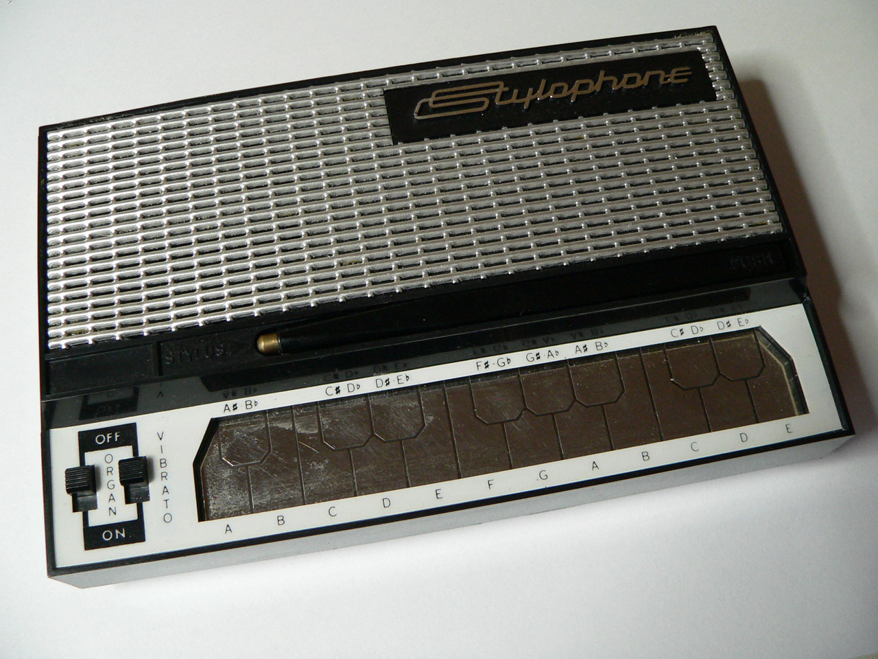
Original 1968 Stylophone
Hardware
Overview
There are a number of circuit diagrams of the Stylophone available on the web, however none of these diagrams seemed to match the Stylophone version I had. Researching on the web revealed that there were at least 3 versions of the original Stylophone. The first had individual resistors controlling the pitch output, then there were two further versions which used ‘resistor modules’ one with white modules and a later one with orange modules. The version I have is the white module version.
I found the following diagram on the web which seems to show exactly the same model of Stylophone as I purchased:
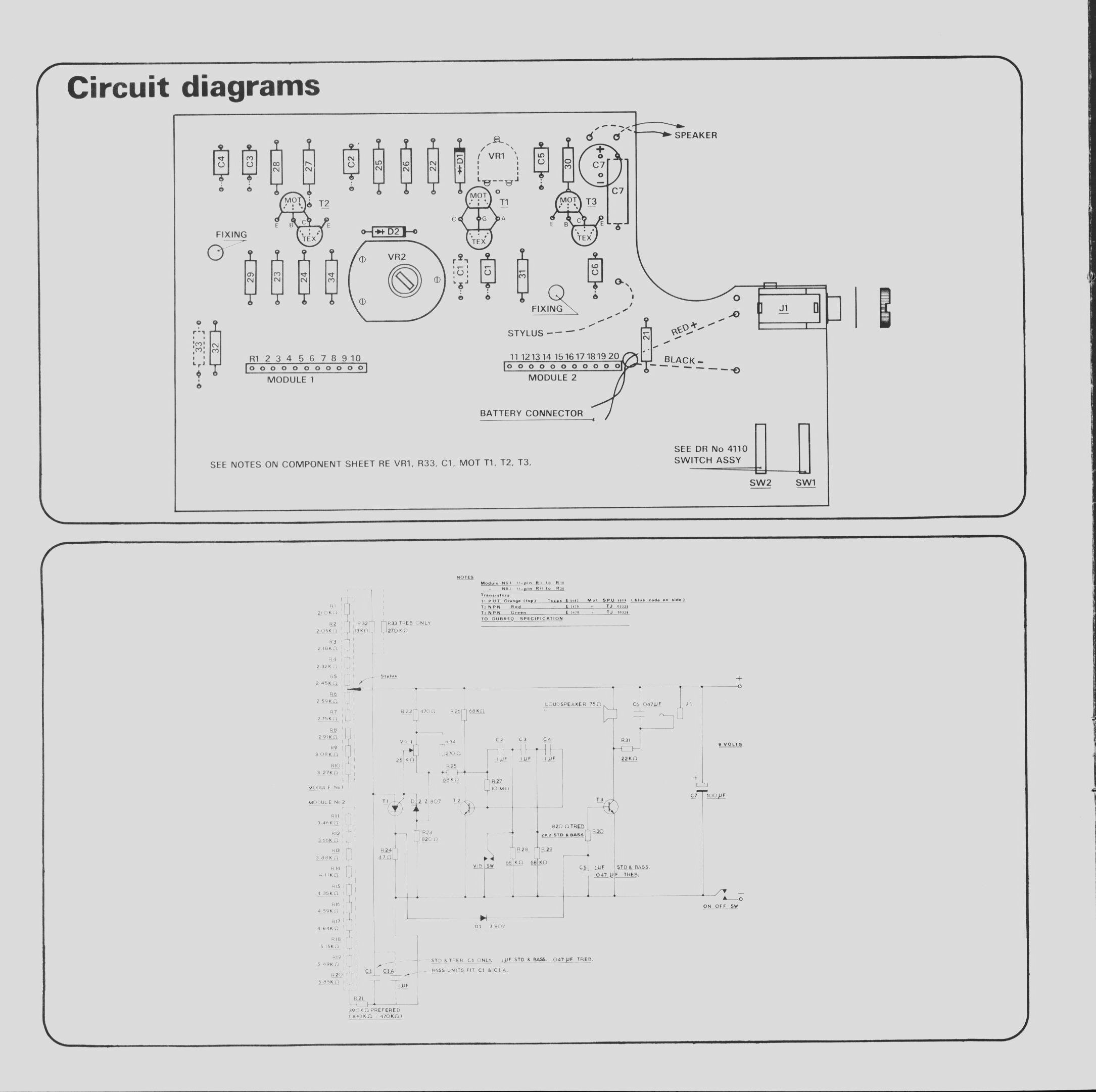
Original Stylophone schematic
Interestingly, although the top half of the diagram matched the version of the Stylophone I had, the circuit diagram did not and seems to show an earlier variant of the Stylophone. By tracing the PCB tracks I was able to reverse-engineer my Stylophone into the following schematic diagram:
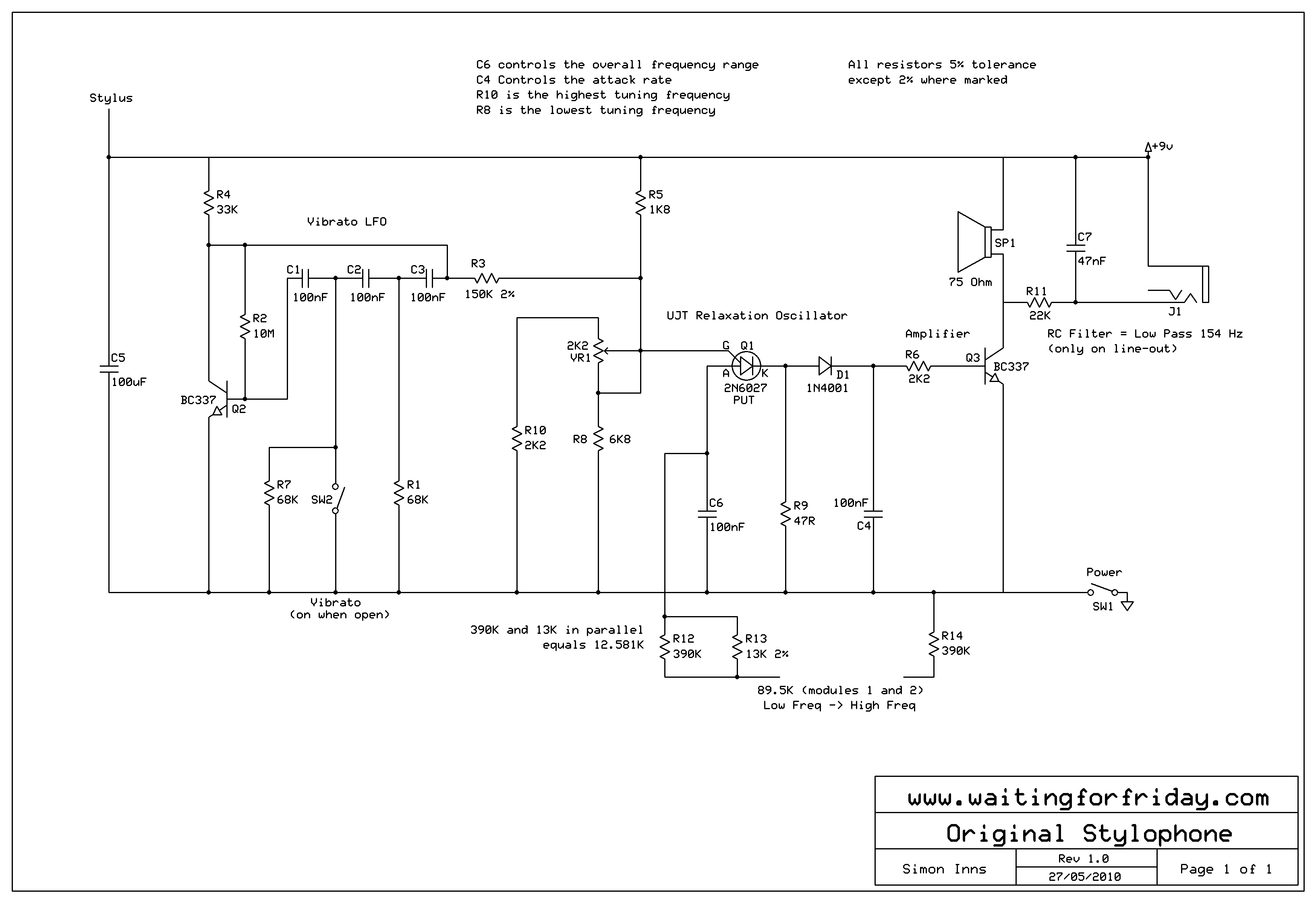
Reverse Engineered Stylophone Diagram
I’ve added some notes to the diagram explaining the functions of the various parts. Since there were no markings on the original transistors or PUT (Programmable Uni-junction Transistor) I replaced them with modern equivalents. For the PUT the choice of replacement was quite limited since there are not that many modern PUTs produced. To test the schematic I built it on a breadboard and compared the output to the original (using an oscilloscope) and the result was surprisingly close to the original. You can quite easily use the circuit diagram above to build your own Stylophone (I did and it worked well).
Relaxation Oscillator Output
To understand why the original Stylophone sounds so different from the 555 timer based versions you only need to look at the ‘shape’ of the output from the PUT to see the unique waveform which a relaxation oscillator produces:
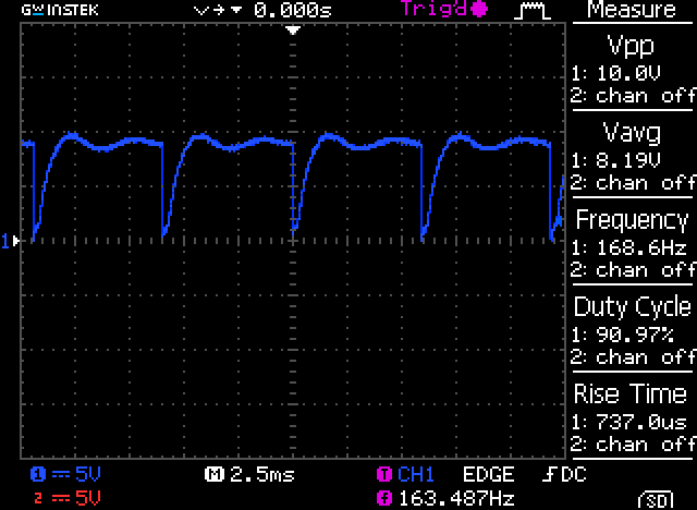
UJT output
Resistor Ladders
The two resistor modules on the circuit had the following resistance values (in Kohms):
- Module 1
- 21
- 2.05
- 2.18
- 2.32
- 2.45
- 2.59
- 2.75
- 2.91
- 3.08
- 3.27
- Module 2
- 3.46
- 3.66
- 3.88
- 4.11
- 4.35
- 4.59
- 4.84
- 5.15
- 5.49
- 5.85
Frequency ranges
The following table shows the note frequencies for the Stylophone with the tuning potentiometer on minimum, maximum and with note A3 tuned to 220Hz (all measurements were taken using a frequency meter). Also included in the table are the ‘actual’ frequencies of the notes as a comparison:
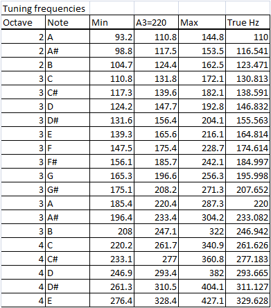
Stylophone frequencies
Vibrato
The vibrato for the Stylophone is generated by a low-frequency oscillator made with a transistor and several capacitors which produces a triangle/sine wave (when the vibrato switch is open) which is fed into the frequency control voltage operating the UJT to produce the warbling effect. The following picture shows the LFO output on an oscilloscope:
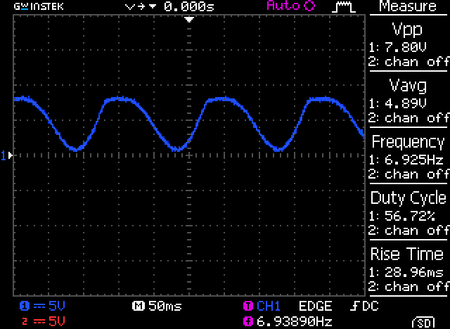
LFO output
The frequency of the vibrato signal is approximately 7Hz. As the vibrato generator takes a little time to ‘charge’ there is a delay of 0.5 seconds between switching on the vibrato and the altered signal being seen at the relaxation oscillator output.
The following table shows the effect of the vibrato on the output signal. The Stylophone was tuned so that A3 produced 220Hz and then a frequency meter was used to measure the maximum and minimum frequency produced for each note, the positive and negative variance was then calculated (shown in Hz):
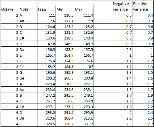
Stylophone Vibrato
As can be seen from the table there is a greater variance as the frequency increases and the negative and positive variance is fairly even across the frequency range.
Line-out low-pass filter
An interesting feature of the circuit is the line-out for connecting the Stylophone to an external amplifier. There is a passive 154Hz low-pass filter on the line-out which is not used by the internal speaker. This means that the line-out sounds noticeably different from the speaker output (which explains why music artists which used the Stylophone held it up to a mic and played it rather than just amping the device directly).
Technical Information
Relaxation Oscillator
To understand the relaxation oscillator and its characteristics we must look at the parts of the oscillator in more detail. The PUT (Programmable Uni-junction Transistor) is ‘programmed’ by the voltage present on the gate (G). The gate voltage is supplied by a classic resistor voltage divider; however the voltage divider also contains a potentiometer which allows the programming to be changed (in this case the programming defines the overall tuning of the Stylophone).
If we consider Ohm’s law for the voltage divider we see that Vout = (Z2 / (Z1 + Z2)) x Vin where Z1 is the positive-side resistance and Z2 is the negative-side. Looking at the original Stylophone diagram we can see that Z1 is 1800 ohms. Z2 consists of 2 resistors and a potentiometer (R8, R10 and VR1). In this configuration the Z2 resistance can be varied between 1662.22 and 2671.43 ohms (note: Z2 = 1/(1/(R10 + VR1)+1/R8) where VR1 is 0-2200 ohms).
The PUT only allows power to flow between the Anode and Cathode if the Anode voltage exceeds the gate voltage (actually, for the 2N6027, the A has to exceed G by 0.35V) and the charging and discharging of the capacitor on the Anode is what causes the oscillation to take place.
To calculate the given frequency of the relaxation oscillator we must first calculate η (eta) which is the intrinsic stand-off ratio of the PUT. Eta is given by the formula: η = Z2 / (Z1 + Z2). Since Z2 is variable this gives a possible range of 0.48 to 0.60.
The frequency of the relaxation oscillator is given by the formula (Where R and C are the resistor and capacitor connected to the anode of the PUT):
- Frequency = 1 / (R x C x ln(1/(1 – η)))
So if we choose our lowest and highest value for η of 0.48 to 0.60 and we take the value of C from the circuit diagram (100nF) we can calculate the frequency range of the Stylophone from the resistor values across the keypad. From the circuit diagram we can see that the minimum possible value for R is 33.581K and the maximum is 102.081K.
This gives minimum and maximum frequency ranges of:
- Fmin = 1 / (102.081K x 100nF x ln(1/(1- 0.48))) = 149.76 Hz
- Fmax = 1 / (33.581K x 100nF x ln(1/(1- 0.48))) = 455.25 Hz
- Fmin = 1 / (102.081K x 100nF x ln(1/(1- 0.60))) = 107.66 Hz
- Fmax = 1 / (33.581K x 100nF x ln(1/(1- 0.60))) = 327.27 Hz
The ‘standard’ Stylophone tuning supports A2 to E4 or 110Hz to 329.628Hz and the calculation shows a possible range of 107Hz to 455Hz (of course, in the real circuit there are tolerances and other issues which may effect this).
Bass and Treble Stylophones
Sources on the web show that the Stylophone was also designed to support two other tunings for a bass Stylophone and a treble Stylophone.
For the bass Stylophone the 100nF capacitor on the anode of the PUT is placed in parallel with C6 (100nF) capacitor (giving 200nF) which means the frequency range is altered according to the following calculations:
- Fmin = 1 / (102.081K x 200nF x ln(1/(1- 0.48))) = 74.88 Hz
- Fmax = 1 / (33.581K x 200nF x ln(1/(1- 0.48))) = 227.62 Hz
- Fmin = 1 / (102.081K x 200nF x ln(1/(1- 0.60))) = 53.83 Hz
- Fmax = 1 / (33.581K x 200nF x ln(1/(1- 0.60))) = 163.63 Hz
The ‘bass’ tuning supports A1 to E3 or 55Hz to 164.814Hz.
For the ‘treble’ tuning the C6 (100nF) capacitor on the anode of the PUT is replaced with a 47nF capacitor which means the frequency range is altered according to the following calculations:
- Fmin = 1 / (102.081K x 47nF x ln(1/(1- 0.48))) = 318.64 Hz
- Fmax = 1 / (33.581K x 47nF x ln(1/(1- 0.48))) = 968.61 Hz
- Fmin = 1 / (102.081K x 47nF x ln(1/(1- 0.60))) = 229.06 Hz
- Fmax = 1 / (33.581K x 47nF x ln(1/(1- 0.60))) = 696.31Hz
The ‘treble’ tuning supports A3 to E5 or 220Hz to 659.255Hz.
Attack Rate
The combination of the diode (D1) and the capacitor (C4) control the ‘attack’ rate of the sound output. When a note is first ‘pressed’ the capacitor (C4) starts charging. This causes the volume level to gradually increase rather than just going from nothing to full volume.
In the ‘treble’ version of the Stylophone C4 is 47nF rather than 100nF which causes a faster attack rate.
Vibrato
The vibrato is supplied by a classic RC Oscillator circuit (also known as a phase-shift oscillator). It consists of 3 RC networks each providing 60 degrees of phase-shift resulting in a total shift of 180 degrees. The RC Oscillator is simple to simulate and should provide around 8.5Hz with a 4.2V P-P sine wave (Peak-to-Peak) under ideal conditions (the actual frequency is also affected by the setting of VR1). The connection of the RC Oscillator to the PUT’s gate will also vary the oscillators output slightly.
The vibrato effect is provided by the RC Oscillator offsetting the PUT’s η (eta) value. The 4.2V P-P means the variation in frequency should be fairly even above and below the intended frequency of the relaxation oscillation. When SW2 is closed the RC Oscillation circuit outputs a constant voltage which is approximately half of the P-P voltage when oscillating.
MP3 Sample
The following MP3 format sample is recorded using a microphone held directly over my original Stylophone. Apologies in advance for my amateurish playing, but you should be able to get a good feel for the sound of the original device complete with the tapping and clicking of the stylus as it is played:
Stylophone Manual
My Stylophone came with both the original instruction manual and a Rolf Harris music sheet. Both have been scanned and converted into PDF files which you can download using the following links:
The Original Stylophone Manual (PDF):
Your chance to play along with Rolf Harris (PDF):