RC Servo Switcher
Contents
Some fellow members of The Abbenay Hackspace (an open hacker space based in Stockholm, Sweden) are embarked on an ambitious project with the aim of being the first to build an autonomous sailing robot which is capable of circumnavigating the Earth.
The project is currently in the early prototyping stages and this RC Servo Switcher project is designed to allow them to regain control over the prototype boats in the event that the on-board computer fails in any way.
The servo switcher is designed as an aid for anyone who wishes to convert a remote control vehicle into an autonomous vehicle, in this case the project is a sailing boat, however the design can be easily expanded to work with cars, planes or helicopters.
Please note: I make no guarantees about the performance of this board. Make sure you test it properly with your radio equipment before entrusting the safety of your robot to it. At the present time it has only been lightly tested – you have been warned!
YouTube Demonstration Video
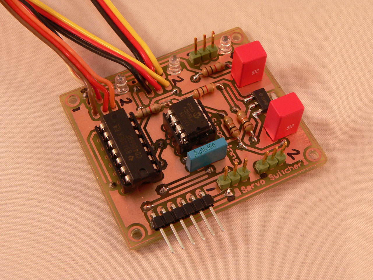
The RC Servo Switcher Board
The servo switcher allows manual fail-over control of an autonomous vehicle using the original radio control system.
A radio control system controls the servos using a series of pulses using a technique known as Pulse Width Modulation. Longer and shorter pulses instruct the servo as to which position it should be in. When the transmitter is turned off the receiver will either output nothing to the servos or a stream of random pulses due to background interference, this causes the servos to jitter around randomly.
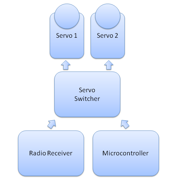
The servo switcher allows you to connect both the radio control receiver and another controller device, such as a microcontroller, simultaneously to the same servos. In the demonstration video I used a simple servo tester, which moves each servo in turn, in order to simulate the external microcontroller system.
The servo switcher monitors one channel of the radio control receiver using the Capture/Compare module on the PIC12F683. This allows the servo switcher’s on-board microcontroller to time the incoming pulses. If the incoming pulses are irregular or not present, the servo switcher uses a 4066 quad analogue switch IC to route the microcontroller servo signals to the servos. If the radio control transmitter is powered on the servo switcher detects the valid control pulses and switches over to the radio control signal disconnecting the microcontroller signals.
This means that if the microcontroller fails for any reason and the vehicle goes out of control, you can simply switch on the radio transmitter and take over the vehicle. Since the servo switcher is effectively passive (until the radio control transmitter is turned on it has no effect on the control circuitry) you can use it during software development and testing and then simply remove it and the radio receiver from the finished autonomous vehicle. By adding more 4066 ICs you can switch as many channels as you like. Each additional 4066 IC allows you to switch 2 more servo channels.
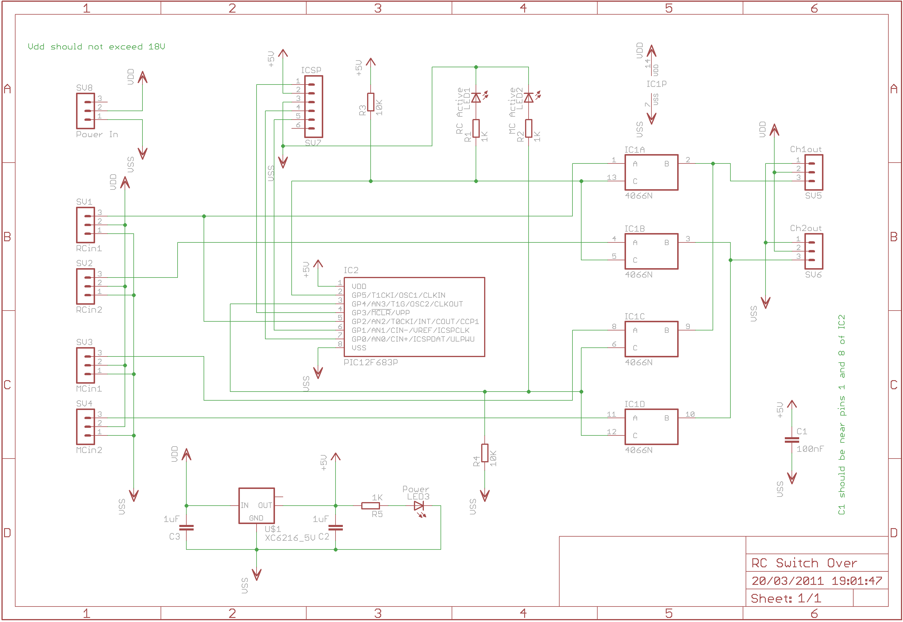
Circuit Schematic
The following diagram shows the circuit schematic for the RC Servo Switcher:
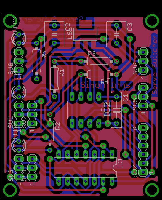
The PCB is designed to be as simple and compact as possible. It also includes 4 mounting holes so the circuit can be easily secured to the autonomous robot:
Files for download
Below you will find the project files including the HiTech C firmware and the Eagle CAD schematic and PCB files:
The PCB artwork and schematics in Eagle CAD format:
The PIC12F683 firmware source code (for HiTech C):