AVR ATmega32U4 USB Development Board
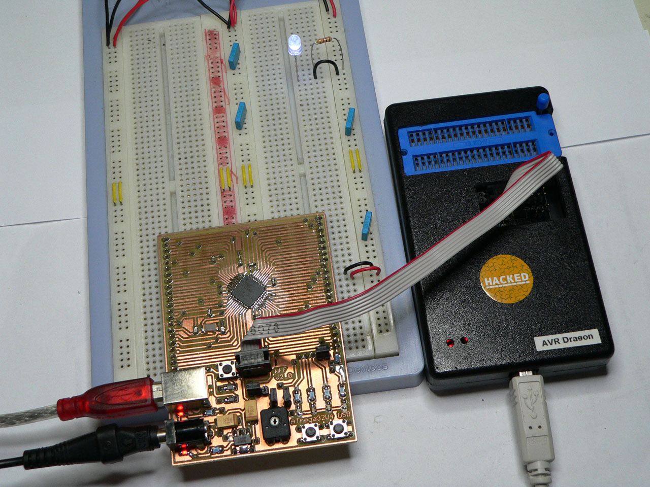
Recently I’ve started working with the Atmel AVR range of microcontrollers. The relatively new range of USB capable ATmega chips are an excellent choice for USB device development, however they are only available in surface-mount packages which represents a barrier to a lot of hobbyists since you cannot simply plug the chip into a breadboard for prototyping.
There are a range of commercially available solutions for this such as the [http://www.pjrc.com/store/teensy_pins.html Teensy] and the [http://www.sparkfun.com/products/10277 Sparkfun ATmega8U breakout board], however I wanted to have a development board which was possible to make using UV or toner-transfer methods and which could be hand soldered.
In addition, when prototyping, it is useful to have a set of common interface components (LEDs, switches, etc.) which can be easily enabled and disabled as required. Lastly I wanted the board to support both bus-powered and self-powered applications (something which most of the commercial boards do not easily allow).
If you don’t feel up to the SMD soldering and want something simpler, there is also a design below based on the Teensy 2.0 board which is ATmega32U4 based which you can either build or just recreate on a breadboard.
The ATmega32U4 USB Development Board
Building the ATmega32U4 USB Development Board
The circuit schematics for the development board have been drawn in Eagle CAD and the files for both the schematic and the board are available below.
Here is the circuit schematic for the board:
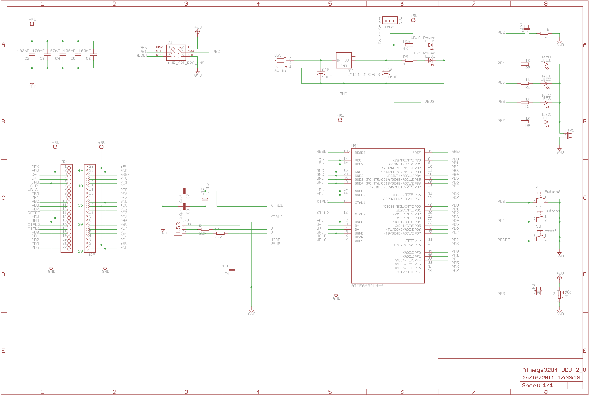
The ATmega32U4 USB Development Board Schematic
As you can see from the diagram all of the on-board peripherals are connected to physical ‘jumpers’ allowing them to be turned off (except for the switches which are naturally passive when not pressed). The reason for this is that under the development board are 2×22 pin SIL headers which allow you to plug the development board directly into a breadboard to allow rapid prototyping.
You can also select between bus-powered and self-powered using a jumper. The board has a 5V 800mA regulator which can be powered by any generic 9V 1000mA supply (centre-positive jack). Both the regulator and the ATmega32U microcontroller are heavily decoupled to ensure stable operation even on a breadboard. The board can also supply 5Vs to the breadboard (you simply connect the Vdd and Vcc pins from the SIL as appropriate).
Since I wanted the to be able to make the board myself I needed to ensure that the track-width and via sizing was appropriate for making the board at home. Also care was taken to ensure that all soldering of components could be achieved without the use of wave-soldering (i.e. there are no inaccessible top-solder joints for any of the components).
As you can see from the schematic the board contains 2 power status LEDs (showing the presence of VBUS power and local power), 4 LEDs for general use, 2 general use switches, a reset switch and a 10K potentiometer for experimenting with ADC. In addition there is a jumpered 1K resistor on the hardware boot pin to allow better compatibility with the various USB boot-loaders.
For the USB connector I used a full-size type B socket which is a lot more sturdy than the micro and mini B connectors (since the cable gets plugged in and out a lot on a development board).
Here is the resulting PCB artwork for the board:
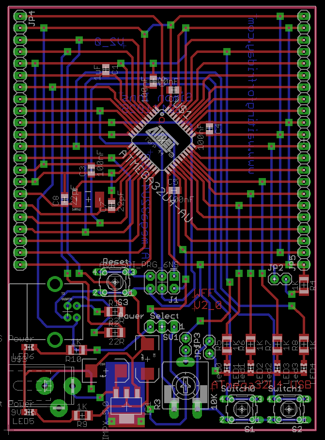
The ATmega32U4 USB Development Board
A Teensy 2.0 Based Development Board
The Teensy 2.0 is an ATmega32U4 based breakout board for USB applications. In order to make it as flexible as possible (and compatible with the UDB above) I’ve designed a simple circuit which adds the required input/output components as well as a programming header for the ATmega.
Here is the circuit diagram:
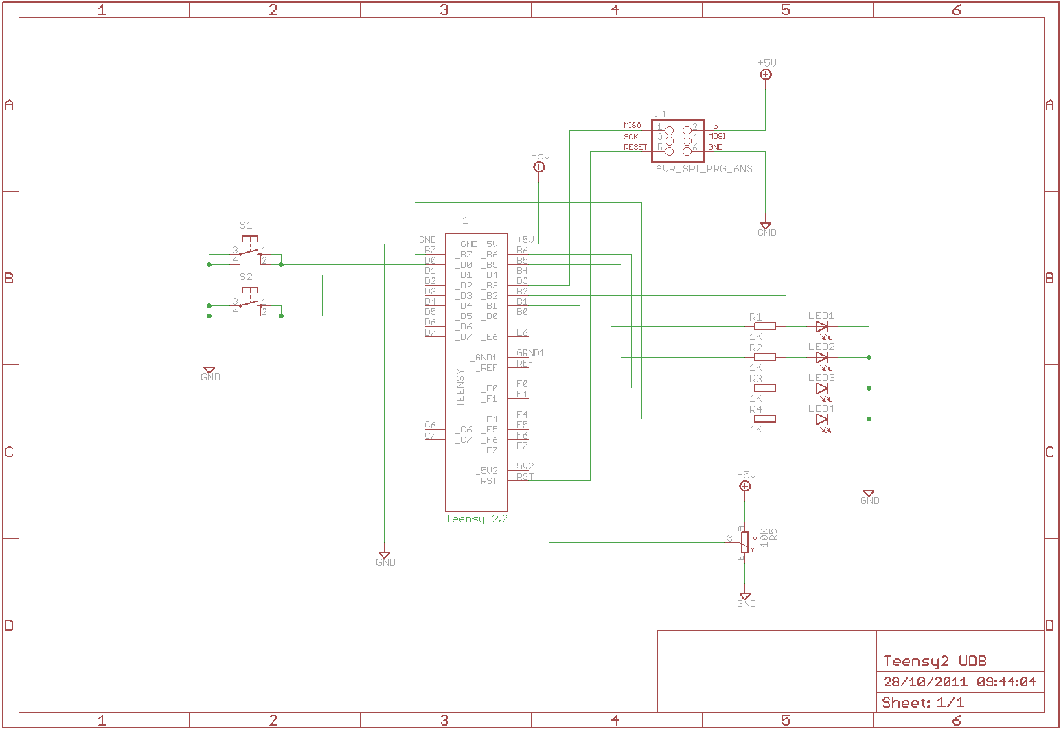
Teensy 2.0 UDB Schematic]
It’s perfectly possible to take a standard Teensy 2.0 (with header pins) and place it in a breadboard. You can then add the required components according to the schematic diagram. If you are happy with making single-sided through-hole PCBs I’ve made the following circuit board to allow you to quickly mount and use the Teensy:
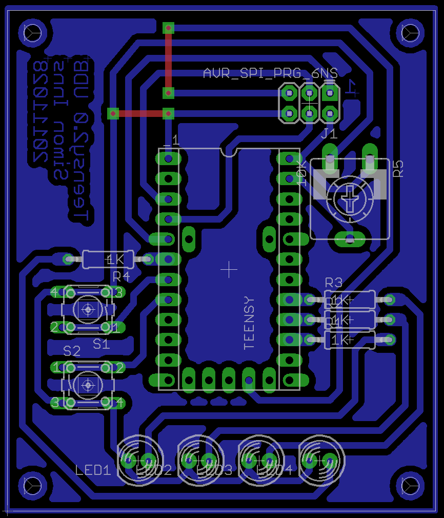
Teensy 2.0 UDB PCB
I’ve taken the Teensy 2.0 footprint from PJRC’s website and extended the pads (and fixed the drill-diameters) in order to make the foot-print more friendly to hand-soldering. In addition I’ve used wide traces with good clearance to make the PCB as easy as possible to print. The programming header is offset to the right so that it doesn’t interfere with the USB cable.
Files for download
In the following zip file you will find the schematics and PCB files in Eagle CAD format:
The ATmega32U4 USB Development Board Eagle CAD files:
ATmega32U4_USB_Development_Board_2_0_Eagle
The Teensy 2.0 USB Development Board Eagle CAD files:
For USB stack examples and software I recommend the excellent LUFA stack from Dean Camera available here.
For USB Generic HID development please take a look at my USB Generic HID Open Source Framework for Atmel AVR and Windows