Controlling LED brightness using PWM
Contents
Pulse Width Modulation or PWM is a term you hear a lot if you are interested in controlling power output using a microcontroller. It has many applications, although one of the most popular amongst hobbyists is controlling the brightness of LEDs.
In this tutorial we will cover the basic principles behind PWM and how it can be used for LED brightness control including fading out LEDs rather than just turning them on and off.

This article will focus on some of the more specific details of the PIC18F range of microcontrollers; however the techniques and principles are the same for all other microcontroller products. Some microcontrollers include PWM modules which perform all of the hard work for you; however this article focuses on the more universal (and scalable) technique of using interrupts.
Video Tutorial
This tutorial is primarily designed as a video tutorial. You can watch the full video on LBRY:
Introduction
To control the brightness of an LED you can vary the power which is sent to the LED, for example using a potentiometer (variable resistor), the more power the LED receives the brighter it is, the less power it receives the dimmer it is. Microcontrollers are digital, meaning they only have two ‘power’ states, on and off. Although it is possible to supply a varying power from a microcontroller (using a Digital to Analogue Converter (DAC)) this usually requires an additional chip.
PWM provides the ability to ‘simulate’ varying levels of power by oscillating the output from the microcontroller.
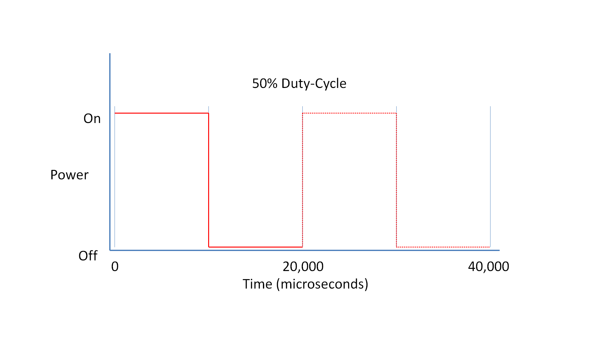
If, over a short duration of time, we turn the LED on for 50% and off for 50%, the LED will appear half as bright since the total light output over the time duration is only half as much as 100% on. The important factor here is the ‘duration’, if we turn the light on and off too slowly the viewer will see the flashing of the LED not a constant light output which appears dimmer. The pulsing width (in this case 50%) is the important factor here. By varying (or ‘modulating’) the pulsing width we can effectively control the light output from the LED, hence the term PWM or Pulse Width Modulation.
When using PWM it’s important to consider how slowly we can ‘flash’ the LED so that the viewer does not perceive the oscillation. The eye’s inability to see rapid oscillations of light is caused by our ‘persistence of vision’ which means, in very simple terms, we see the light as on even after it has turned off. This technique is how televisions display a seemingly moving picture which is actually made up of a number of different still frames displayed one after the other very rapidly.
The minimum speed of an LED oscillating which can be seen by the human eye varies from person to person. However, for the purposes of this article, we will use a minimum speed of 50Hz, or 50 times per second (the same speed as used by European televisions).
Duty-Cycle
When using PWM there are certain terms which you will come across again and again. The most important term is ‘duty-cycle’. The duty-cycle refers to the total amount of time a pulse is ‘on’ over the duration of the cycle, so at 50% brightness the duty-cycle of the LED is 50%. The ‘cycle’ itself is measured (usually) in Hertz which gives us the cycles-per-second. So at 50Hz our cycle is 1 second divided by 50 cycles, which is 0.02 seconds. Since we are using such small time measurements it’s more useful to use microseconds (there are 1,000,000 microseconds in a second), this gives us a cycle duration of 20,000 microseconds which is 50 cycles per second or 50Hz.
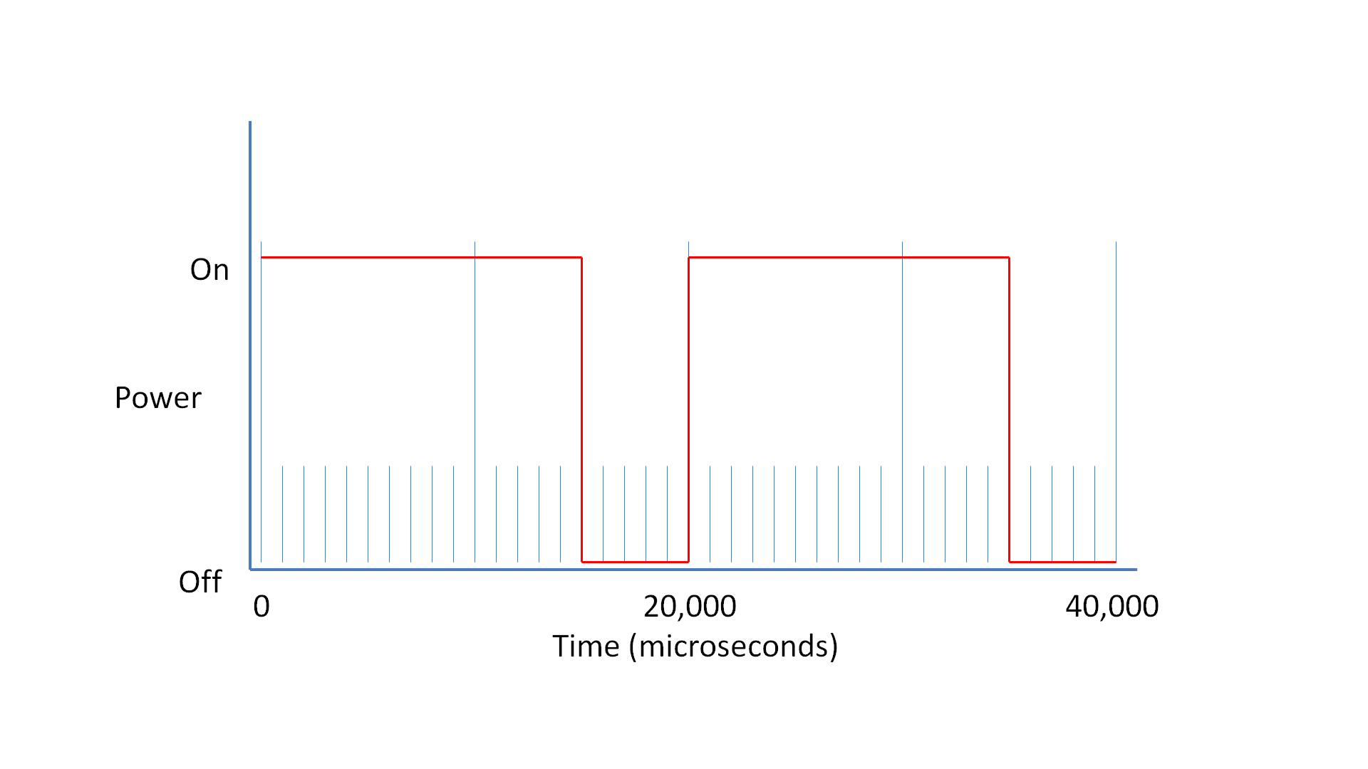
During the 20,000 microseconds we have to turn the LED either on or off depending on the required duty-cycle so, for example, a 75% duty-cycle requires the pulse to be on for 15,000 microseconds and then off for 5,000 microseconds.
PWM Resolution
The accuracy with which we can control the duty-cycle is known as the ‘PWM resolution’. The higher our PWM resolution is, the more levels of ‘brightness’ we can display. However, since the duty-cycle is ‘fixed’ at 50Hz more resolution requires finer timing from the microcontroller. The faster the microcontroller, the smaller durations it can time. Another limiting factor is the code execution, the microcontroller must not only time the ‘interrupt’ which causes the pulse generation, but also run the code which controls the LED output, which must complete before the next interrupt is called. In addition, you probably want your microcontroller to be performing tasks other than LED PWM brightness control, so there has to be some spare execution time between interrupts to do all of the other more general processing tasks.
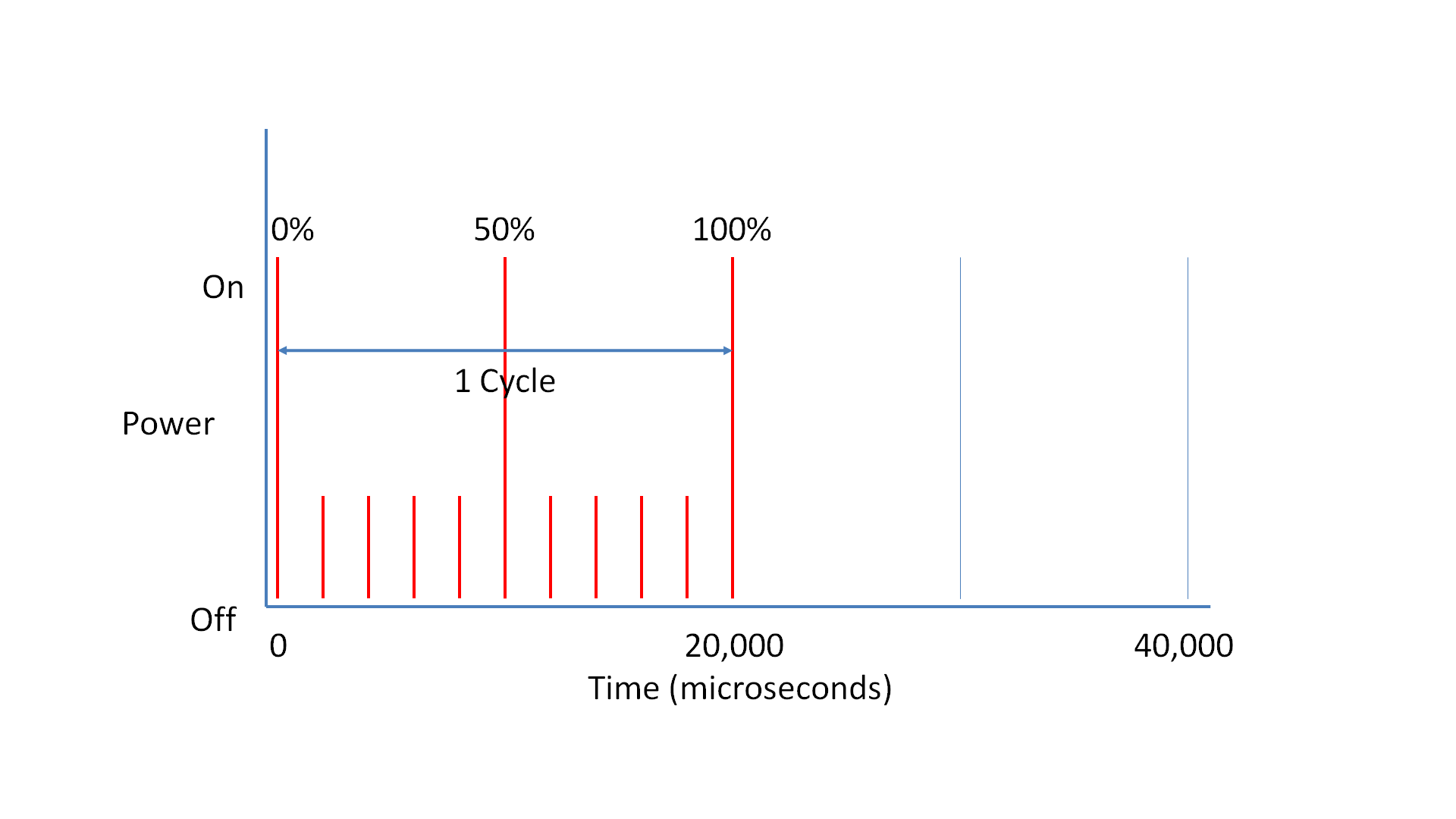
With PWM control of LEDs the primary advantage of higher PWM resolutions is that it results in a smaller difference between ‘off’ and the lowest possible brightness from the LED. For example if our duty-cycle is 20,000 microseconds (50Hz) and our resolution is only 10,000 microseconds, the difference between ‘off’ and the lowest possible brightness will be 50% of the total possible brightness. At a resolution of 2,000 microseconds the difference would be 10% and so on. Overall the ‘PWM resolution’ dictates the number of brightness ‘levels’ we can support between completely off (0%) and completely on (100%). Again, the higher the resolution, the more timing accuracy and processing overhead is required.
For your application the required resolution and overall duty-cycle may vary. Simple displays require very little precision control (and sometimes a little flickering is not the end of the world), for more advanced displays the ability to control levels of brightness might be critical (think of the issue of mixing colours using a RGB LED for example). The trade-off is simple, more control and accuracy requires more and more microcontroller resources.
In this article we will focus on an example which supplies a resolution of 1,000 microseconds over a 20,000 microsecond duty-cycle (or 50Hz with steps of 5% giving us 20 levels of brightness). This level of control and accuracy is suitable for many purposes.
Timing the Interrupt
To perform the PWM using an interrupt we have to call the interrupt once every 1,000 microseconds and decide if the LED should be on or off. To do this we have to set up a timer on the microcontroller which calls the interrupt when it expires.
For this example we will take a Microchip PIC18F4550 microcontroller running at 48Mhz as the example. 48Mhz means the clock of the microcontroller will ‘tick’ 48,000,000 times a second. This is referred to as ‘Fosc’ (the Frequency of oscillation). A PIC18F4550 requires 4 ticks of the clock to process a single instruction. This means the smallest amount of time we can deal with using the microcontroller is a quarter of the clock rate, i.e. 48,000,000 / 4 = 12,000,000 (this is also known as Fosc/4), if there are 1,000,000 microseconds in a second, this means we execute a command around once every 0.0834 microseconds (12 MIPS (Million Instructions Per Second)). Although this is not quite correct in PWM terms since to generate a pulse we would need two commands (on and off) meaning a minimum cycle time of 0.167 microseconds (this effectively limits the highest frequency we can produce in software to 6Mhz, although this is not a very practical maximum).
If the Fosc/4 rate is 12,000,000 this means 1 microsecond of time passes for every 12 processor cycles. This means that 1,000 microseconds is equivalent to 12,000 processor cycles. This is important because with a 1:1 prescaler the PIC’s timers update once every processor cycle (although this is referred to as a 1:1 prescale, it really means no prescale at all). The timer’s prescaler slows down the rate at which the timer’s counter updates, with a 1:2 prescaler it updates once every 2 processor cycles, with a 1:4 prescaler it updates once every 4 processor cycles and so on.
To use an 8-bit timer (you can use a 16-bit timer also if you like) the maximum period the timer can measure is 256 ‘counts’ (0-255). Therefore we have to pick a prescaler value which allows us to time 12,000 processor cycles in less than 256 timer ticks. If we use a 1:64 prescaler we require 187.5 timer ticks to measure 1,000 microseconds:
12 processor cycles per microsecond, so 12 * 1000 = 12,000 processor cycles per 1,000 microseconds: 12,000 cycles / 64 (prescale) = 187.5 timer ‘ticks’
Since we cannot count a ‘half’ we simply round the figure down to the nearest integer (this means are resulting PWM will not be totally accurate, but for the purpose of controlling LED brightness this is not very critical). The higher prescale value we use, the less accurate the timing becomes. This can be corrected by using a 16-bit timer which allows us to count far more ticks and therefore use a lower prescale value.
For a PIC18F4550 this will result in code similar to the following excerpt where the timer0 module is configured, enabled and set to generate a low-priority interrupt:
	// Enable interrupts with priority
	IPEN = 1;

	// Set up timer0
	TMR0IP = 0;			// Set timer0 interrupt to low priority
	TMR0IF = 0;			// Clear the timer0 interrupt flag
	TMR0L = 255 - 187;		// Reset the timer0 counter

	T0CON = 0b11000101;		// Timer0 on, 8-bit and 1:64 prescaler
	TMR0IE = 1;			// Enable the timer0 interrupt

	// Enable interrupts
	GIEH = 1;			// Global enable all high priority interrupts
	GIEL = 1;			// Global enable all low priority interrupts
Once the timer is configured and running we need some interrupt code to decide if the LED should be on or off for the interrupt. Since we have 20 possible brightness levels (and therefore 20 steps of resolution in our PWM generation) we can simply use a counter which counts from 0-19 and is updated once every interrupt. If the brightness of the LED is represented using a number from 0-19 we simply have to check if the PWM counter is higher or lower than the brightness number to see if the LED should be on or off.
// Globals for PWM
unsigned char pwmCounter = 0;
unsigned char ledBrightness = 0;

// Low priority interrupt procedure
void interrupt low_priority lpHandler(void)
{
	// Is this timer0 interrupting?
	if (TMR0IF)
	{
		if (ledBrightness > pwmCounter)
			LED0 = 1; else LED0 = 0;

		pwmCounter++;
		if (pwmCounter > 19)
			pwmCounter = 0;

		// Get ready for the next interrupt
		TMR0L = 255 - 187;	// Reset the timer0 counter
		TMR0IF = 0;		// Clear the timer0 interrupt flag
	}
}
Fading the LED
Since we know the cycle duration of the timer0 timer we can also use this to provide fading effects on the LED. To do this we have to store two values for the LED brightness, one variable to store the actual displayed brightness and another to store the target brightness for the LED. Since we only want fade off (you could adapt this easily to support both fade on and fade off) if the target brightness is higher than the actual brightness, we immediately bring the actual brightness to the same level.
However, for fading off we want to decrement the actual brightness level one step at a time until it equals the target brightness. Since there are only 20 levels of brightness we cannot simply subtract a level on each interrupt call since the interrupt call is too fast for the fade to be perceived by the viewer (20 calls would only consume 20,000 microseconds which is too fast to see).
Instead we keep another counter which counts a number of interrupt calls which should occur in between decrementing the actual fade level. Since we know the interrupt is called every 1,000 microseconds it’s pretty straight-forward to work out how many interrupts we should count to get a desired fading rate. For example, if we want a fade from brightness level 19 to 0 to take 0.5 seconds we simply divide the required time (in microseconds) by the interrupt time of 1,000 microseconds and then by the number of levels. Therefore 0.5 seconds (or 500,000 microseconds) = 500,000 / 1,000 = 500 /20 = 25. This is shown in the following code excerpt:
// Globals for PWM
unsigned char pwmCounter = 0;
unsigned char ledActualBrightness = 0;
unsigned char ledTargetBrightness = 0;

unsigned char fadeCounter = 0;

// Low priority interrupt procedure
void interrupt low_priority lpHandler(void)
{
	// Is this timer0 interrupting?
	if (TMR0IF)
	{
		// Perform the PWM brightness control
		if (ledActualBrightness > pwmCounter)
			LED0 = 1; else LED0 = 0;

		pwmCounter++;
		if (pwmCounter > 19) pwmCounter = 0;

		// Perform fading control
		if (ledTargetBrightness >= ledActualBrightness)
			ledActualBrightness = ledTargetBrightness;
		else
		{
			fadeCounter++;
			if (fadeCounter == 24)
			{
				ledActualBrightness--;
				fadeCounter = 0;
			}
		}

		// Get ready for the next interrupt
		TMR0L = 255 - 187;	// Reset the timer0 counter
		TMR0IF = 0;		// Clear the timer0 interrupt flag
	}
}
Conclusions
Whilst it is perfectly possible to get PWM controls to work with LEDs using pure guess work, calculating the desired optimum values makes more efficient use of the available processor resources allowing you to both do more with the microcontroller and/or control more LEDs simultaneously from the same chip. The same techniques shown here for LEDs can also be used to control motors, analogue meter displays, incandescent light bulbs, etc.
Files for Download
Source-code for both demonstrations: