Rotary Encoder Demonstration
Rotary encoders are very versatile input devices for microcontroller projects, not only do they provide 360 degrees of rotational freedom they also allow digital positioning information to be gained without the use of analogue to digital converters (ADCs). When using rotational encoders in projects it’s possible to use the same encoder to represent a number of different input types, however this requires some form of feedback display to let the user know what information he is inputting and the ‘position’ of the encoder.
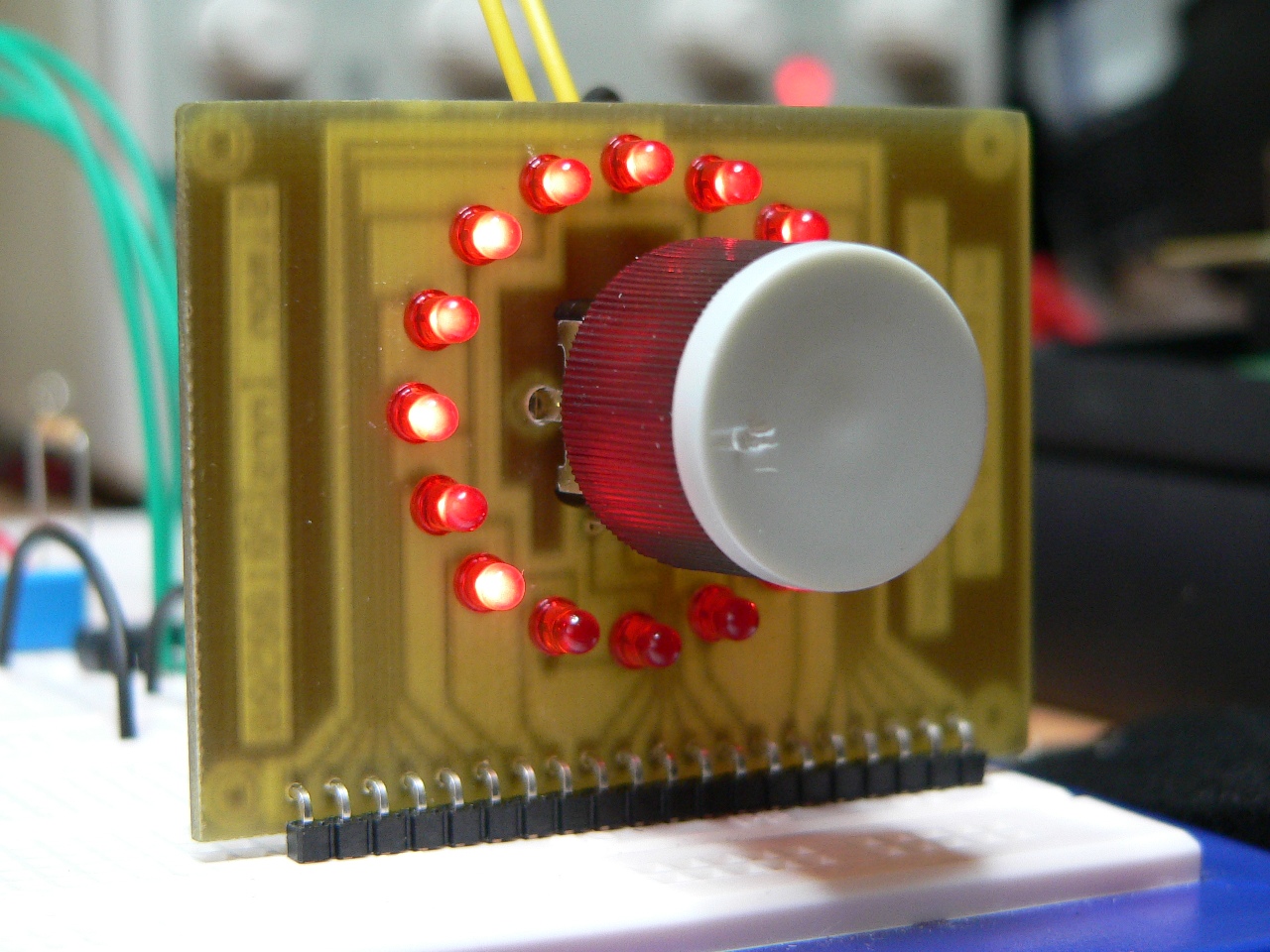
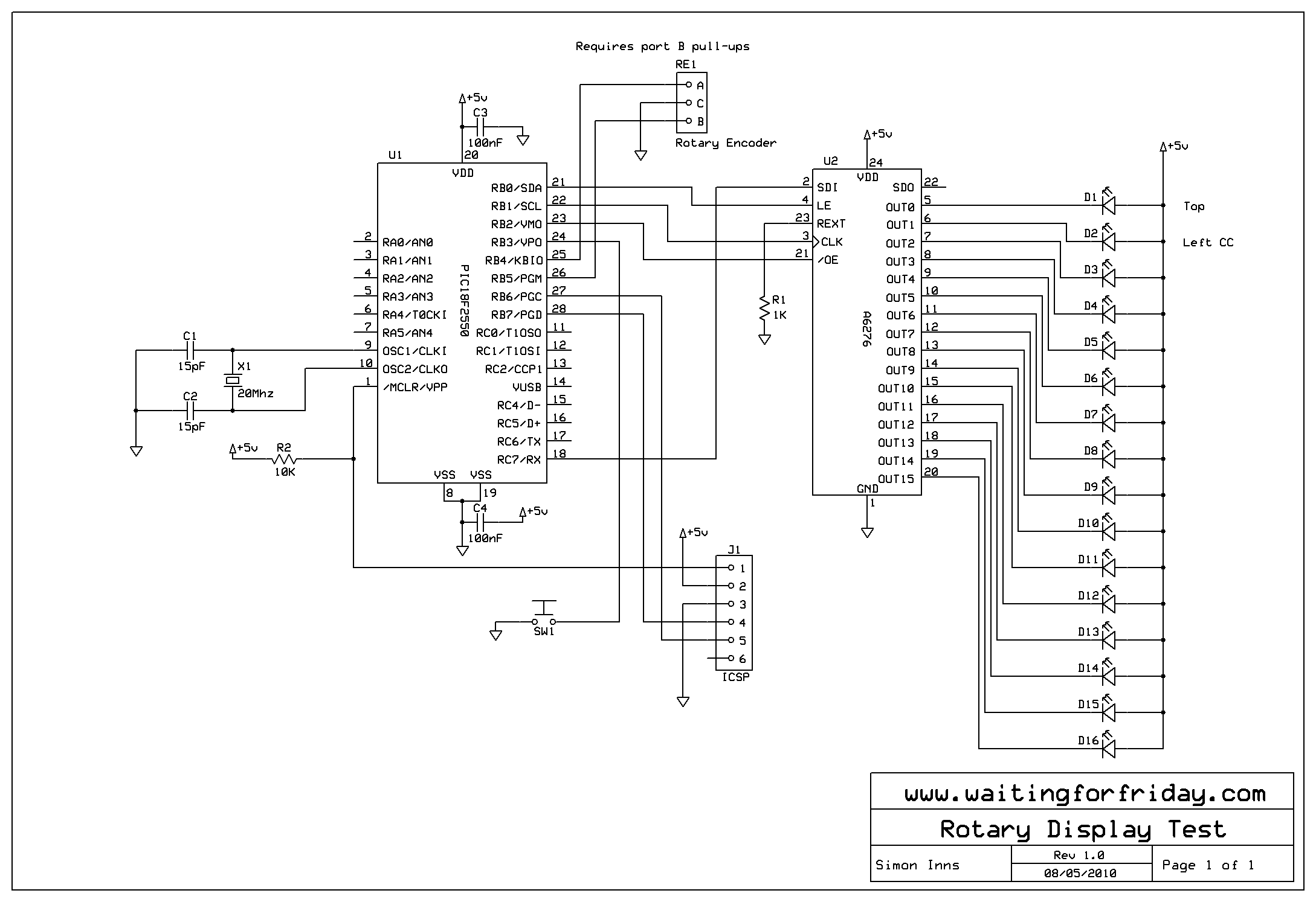
The project is based around a 24 position rotary encoder, 16 LEDs arranged in a circle around the encoder, an A6276 16 LED serial driver IC and the PIC182550 microcontroller.
YouTube Demonstration Video
Rotary Encoder
A rotary encoder has 3 pins usually called A, B and C. The C pin (which is normally the centre pin) should be grounded and both A and B should be connected to the microcontroller with individual pull-up resistors on each input. In this project I used RB4 and RB5 on the PIC to connect the encoder; this has 2 advantages, firstly you can use the PORTB internal weak pull-up (which means you do not need external resistors) and also the PIC provides an ‘interrupt-on-change’ which can be used to monitor the encoder.
LED Display
The LED display consists of 16 3mm red LEDs arranged in a circular pattern around the encoder. I chose normal intensity LEDs since you don’t want the display to annoy or blind the user, also normal intensity LEDs are cheaper and more readily available. The LEDs are connected with common anodes to +5V and the individual cathodes running to the A6276 LED driver IC.
The A6276 is a 16 channel serial LED driver which supports SPI. Although you can see in the video that the LEDs have PWM brightness control, this is actually performed by the PIC (since the A6276 does not have in-built PWM). The A6276 allows you to control far more LEDs than the PIC can handle by itself (since you are limited to a maximum output of 200mA from the PIC) and also the SPI serial connectivity saves port pins on the PIC and makes the design much more scalable if you wish to add more encoders and displays.
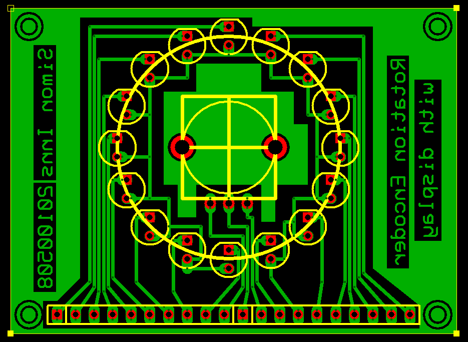
Here is a picture of the PCB artwork used for the encoder and display:
PIC Firmware
The PIC firmware is relatively simple (I borrowed the A6276 PWM driving code from my UltimateSIMON project). It provides 3 types of rotary input and feedback:
- 360 degree position – In this mode the LED display indicates the current ‘position’ of the encoder, the user can rotate the control left and right any number of degrees
- Volume – In this mode the LED display indicates a value which is varied between the minimum and maximum ends of the input range (like a volume control). The LEDs show the current value as a solid bar from zero
- 3 position rotary toggle switch – In this mode there are only 3 positions to choose from. The user selects the desired position by rotating the control left and right.
To understand how the PIC reads the encoder information and communicates with the A6276 please take a look at the source-code provided below.
If required you can easily add a USB interface to this project by combining the firmware with the Generic HID library firmware available Open Source Framework for USB Generic HID devices based on the PIC18F and Windows.
Circuit Schematics
The schematic for the circuit used in this demonstration is as follows:
I built the encoder and display on a simple PCB to allow the correct placement of the LEDs, the rest of the project was built on a breadboard.
Files for download
A zip containing the MPLAB project and source-code (for Hitech C), the schematic and PCB design are also included: