UltimateSIMON
Contents
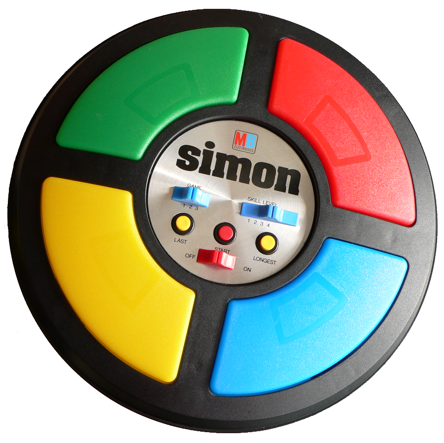
UltimateSIMON is a project which takes a broken MB Electronics SIMON game and replaces the original PCB with a completely custom PIC18F2550 based board with improved sound, lights and the ability to be programmed and customised. There’s even a USB header, in case you want to make the project even more crazy.
There are a lot of broken Simon games available cheaply on sites like ebay, this project lets you breath life into them once again.
Features
The new mainboard not only replaces the original design but also includes a number of extra features to bring this classic game into the new century:
- 12 PWM controlled high-intensity LEDs
- Tactile switches for improved button sensitivity (with full debounce)
- 2 transistor sound amplification
- Digitally controlled volume
- Runs from a single 9V battery or 9V ‘wall wart’ power supply
- ICSP header for easy programming
The new mainboard is designed to fit directly into the lower part of the Simon game’s case without alteration to the case itself. You can (optionally) fit a 2.1mm DC jack to the case to allow the game to be powered by a 9V power supply. The mainboard is designed so that the PSU can be connected without disconnecting the battery. Unlike the original game the mainboard does not required 2 D-cell batteries for operation (since the LEDs consume much less power than the original light bulbs), the LEDs are also far more reliable and long-lasting.
Here is a picture of the new mainboard mounted in the Simon game case:
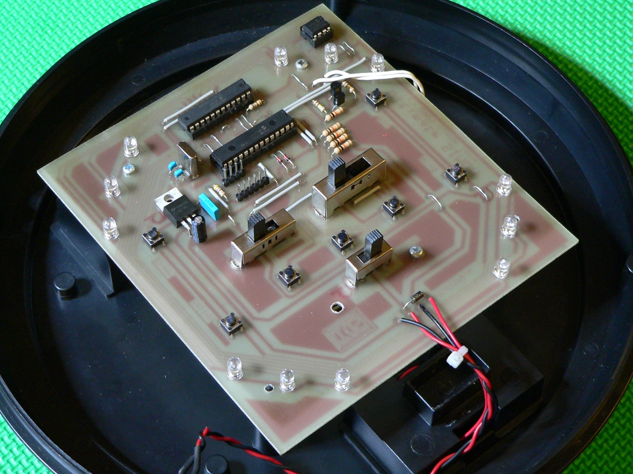
The switches are from the original mainboard and must be carefully desoldered and then re-soldered on to the new board (these switches are impossible to source, but of course you can reprogram the game to operate using only the colour buttons if your original switches are damaged).
In order to make the colour buttons work with the new mainboard you have to remove the springs from the colour lenses and glue the plastic tabs into the lens (ordinary superglue works perfectly). This is because the tactile keyboard switches on the mainboard are raised higher than the originals and also spring back by themselves.
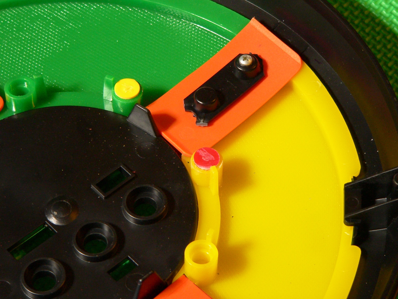
Here is a picture of the modified top part of the case (note that the original case was damaged, so I’ve replaced the main lens springs with a flexible plastic – if your top case is not damaged there in no need to do this):
Mainboard design
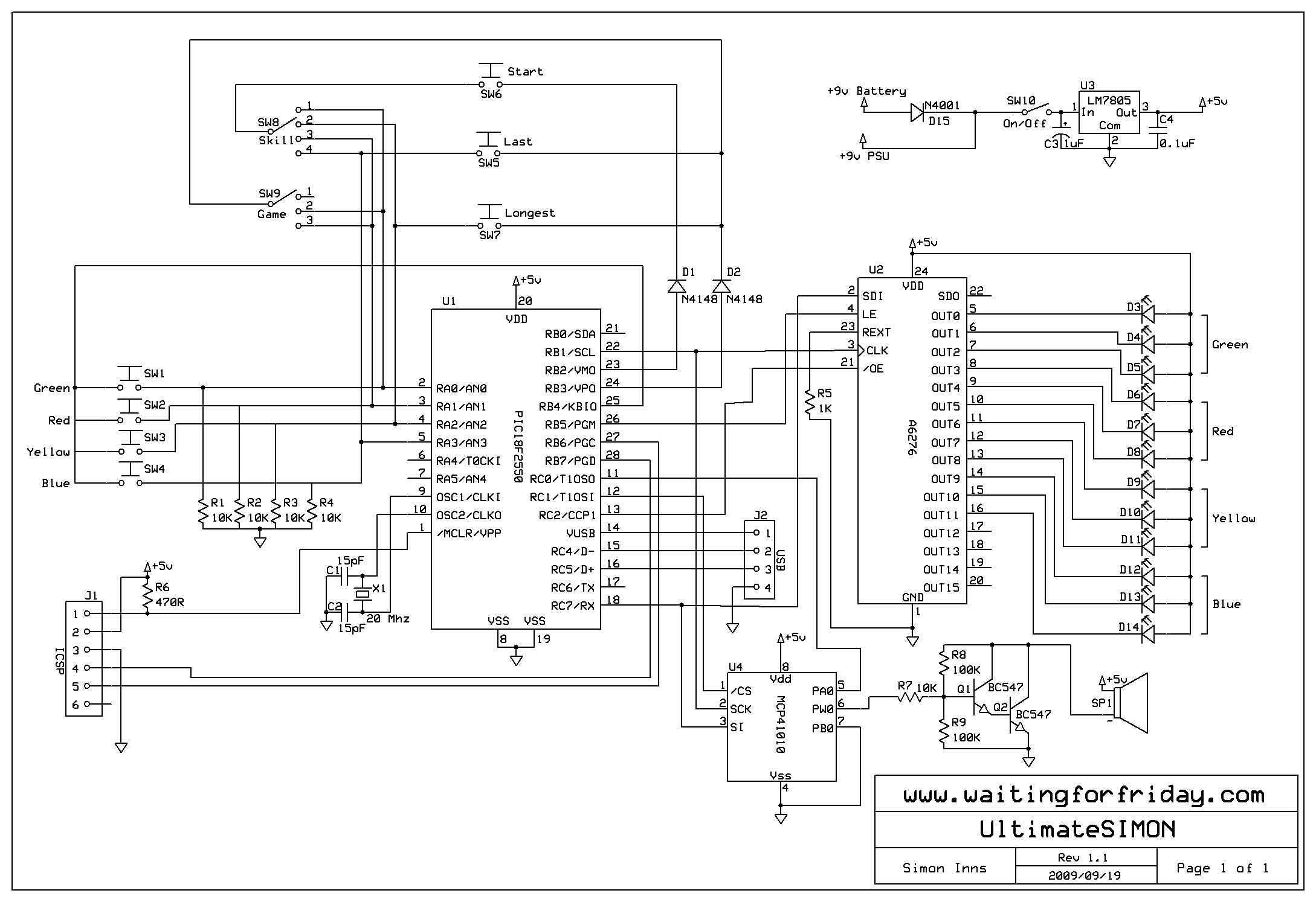
The mainboard consists of a PIC18F2550 (a microcontroller chip), an A6276 serial LED driver and a Microchip MP41010 10K serial digital potentiometer. Both the digital pot and the LED driver are connected to the PIC using SPI serial communication.
Here is a schematic of the mainboard circuitry:
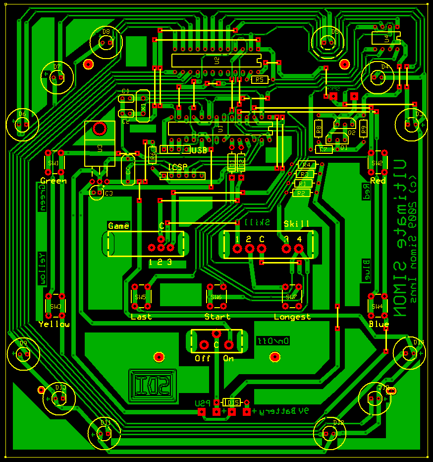
The PCB artwork is designed to allow the PCB to fit into the original case with correct alignment with the colour buttons and switches. It also avoids any of the protruding plastic pins inside the case making it fit neatly without case modification. The original switches will fit directly into the mainboard PCB without modification.
Here is a picture of the PCB artwork:
Software
The software is based on my previous Simon18F project and also my Reverse engineering an MB Electronic Simon game project. I made a few fun modifications to the game including a start up display and tune and new ‘fanfare’ tunes when you win.
I also altered the pitch of the buttons to be pitch-perfect against the bugle-scale which the original game designers planned to use.
You can alter the volume of the game by using the red colour to turn the sound up and the blue colour to turn the sound down. This only works when the game is not in progress.
Take a look at the YouTube video of the game to see it all in action.
Files for download
Please review this site’s Creative Commons licence before downloading any content. The source code is released under the GPL licence.
MPLAB Project zip file containing the source code:
ExpressPCB and ExpressSCH files of the PCB and circuit diagram: