SmallyMouse2 – Universal USB to Quadrature Mouse Adapter
Contents
SmallyMouse2 is a universal USB to quadrature mouse adapter for many 8-bit and 16-bit retro computers and allows the use of modern USB mice on machines such as the Acorn BBC Micro, Acorn Master, Acorn Archimedes, Commodore Amiga, Atari ST and many more. Unlike most existing mouse adapters, SmallyMouse2 implements a fully USB compatible interface (most current adaptors are PS/2 based) this allows the use of any modern mouse including those that use wireless communications.
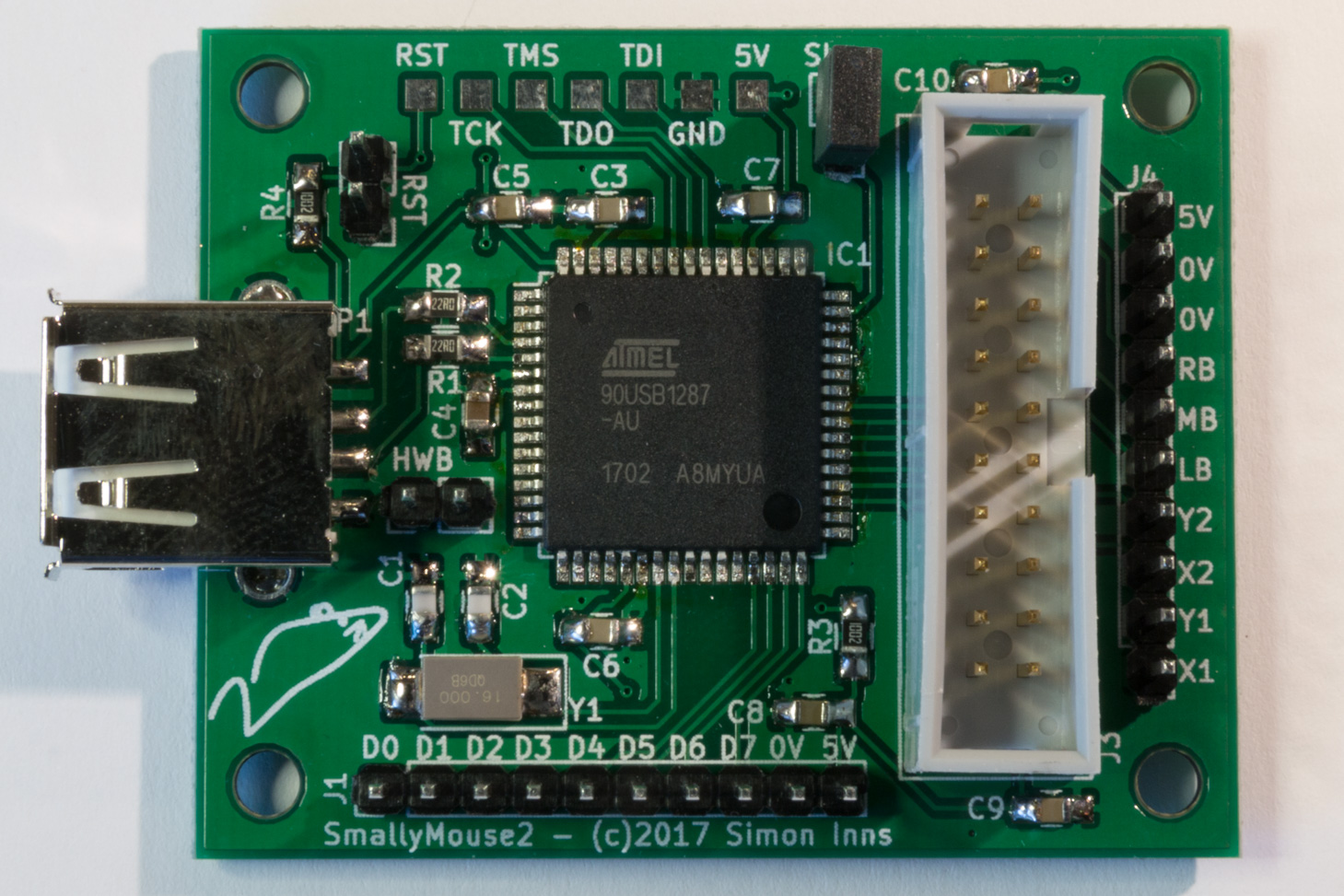
The SmallyMouse2 device
SmallyMouse2 provides a smaller PCB footprint compared to the original SmallyMouse and, in addition, has quadrature output headers suitable for both the Acorn BBC Micro (a 20 pin IDC) and a 10 pin SIL header suitable for custom-made cables for retro computers. SmallyMouse2 also supports the Atmel FLIP DFU bootloader (pre-programmed into the AVR chip by Atmel) and can be flashed via USB allowing both initial programming and firmware upgrades without the need for Atmel programming hardware.
SmallyMouse2 also provides an expansion header with 8 GPIO pins. This allows general purpose IO as well as access to the I2C and UART serial hardware of the AVR microcontroller. This header can provide the ability to add a serial debug console as well as other hardware such as status LEDs and additional configuration switches.
SmallyMouse2 has been tested with the following machines (please see the cable pinout section below for details):
- Acorn BBC Micro model B
- Acorn BBC Master Turbo
- Acorn RISC PC 600
- Commodore Amiga A600
- Atari 520ST
If you have successfully tested SmallyMouse2 with a computer that is not in the list above please leave a comment (stating the exact model of computer and the firmware version either below, or as a GitHub issue for the present firmware release – if this involves a pinout which is not provided below, please send a note of the pinout also if possible).
Hardware
Schematic
SmallyMouse2 uses an AT90USB1287 microcontroller from Atmel that supports both USB device (used for bootloader programming) and host mode (used for mouse support). Host mode support is required as a USB mouse is a device and therefore needs SmallyMouse2 to act as the host computer. The schematic design for SmallyMouse2 is available from GitHub in KiCAD format:
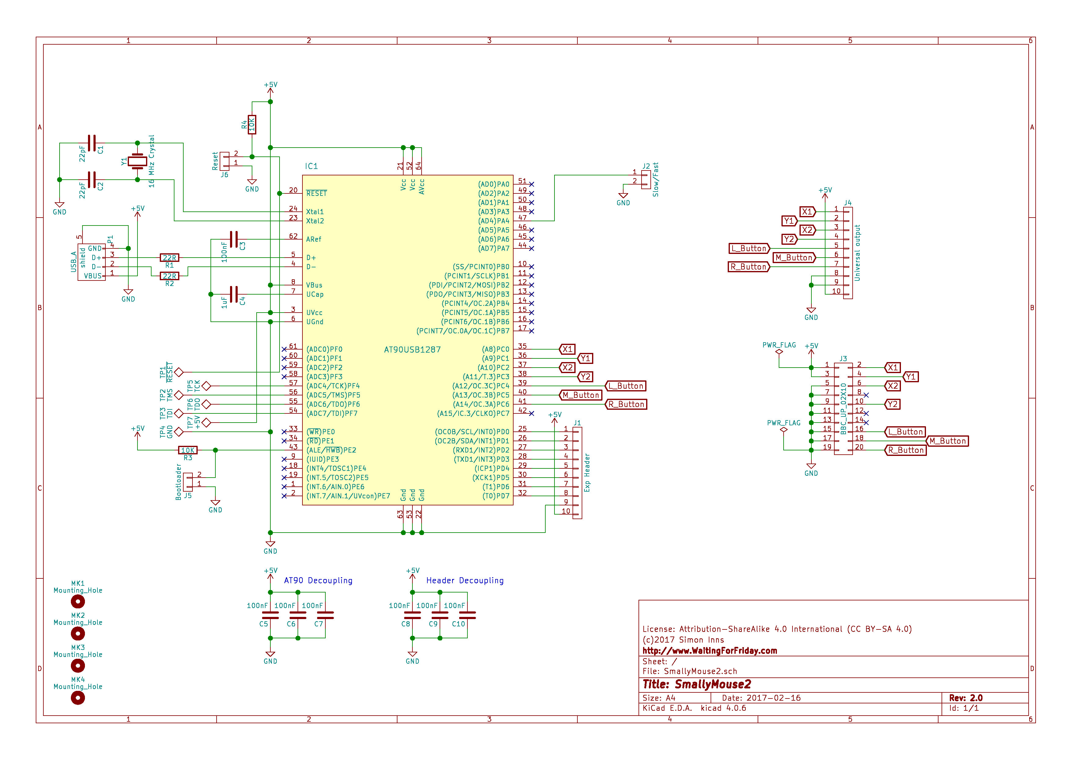
SmallyMouse2 Schematic
For details of the various interfaces provided by the SmallyMouse2 design please see the interfaces section below.
PCB design
The PCB design can be seen in the following picture:
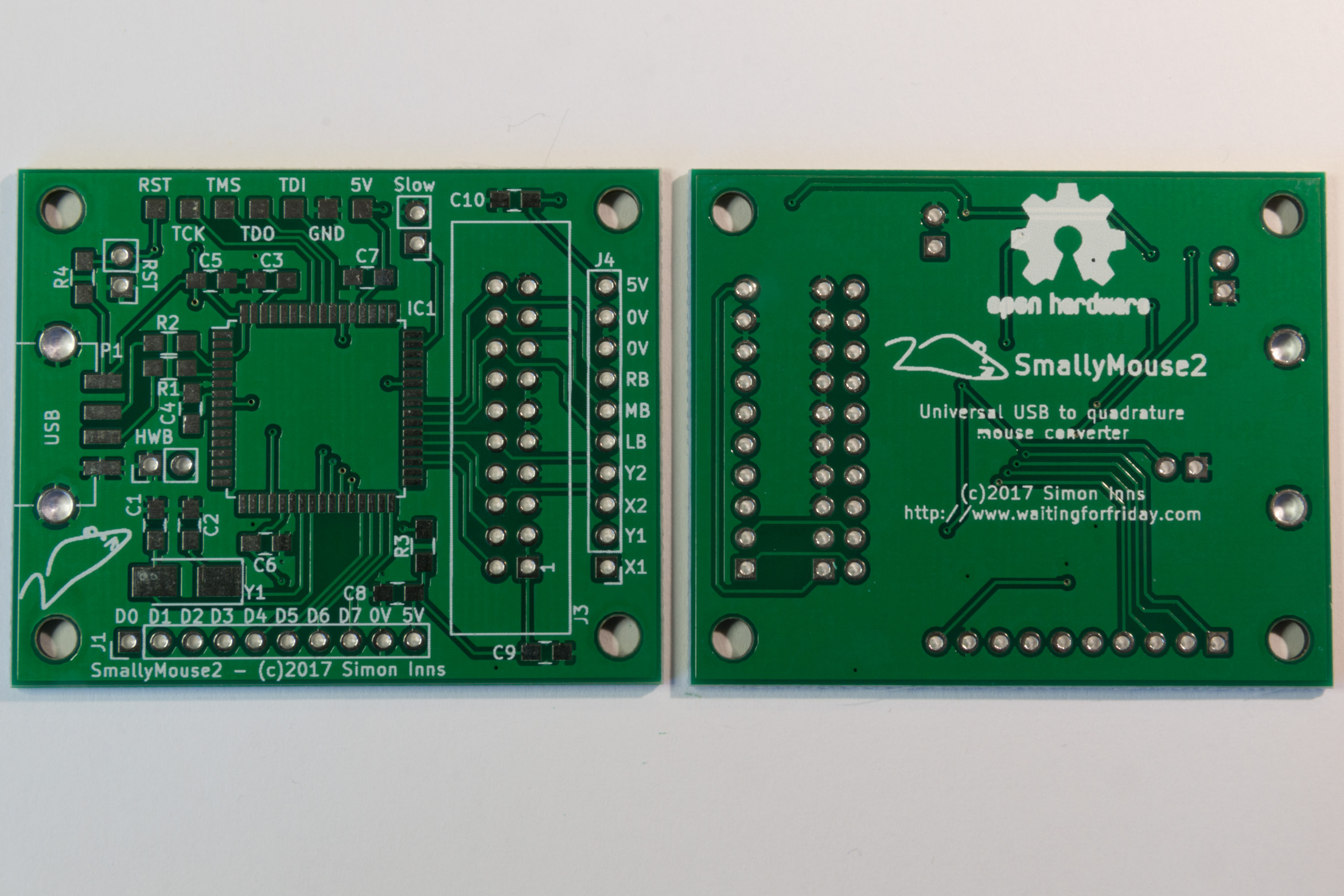
The SmallyMouse2 PCB
The PCB is designed to be fabricated as a double-sided PCB. Due to the tolerances of the traces and vias on the PCB it is recommended that the board is produced by a professional fabrication service. The required Gerber files for fabrication are included in the GitHub project files.
The PCB design also includes 4 mounting holes for M3 size screws or PCB stand-offs. The USB port is extended over the edge of the PCB to facilitate mounting the board inside an enclosure.
All required components are mounted on the top-copper surface of the board to provide compatibility with pick-and-place machines (and to simplify hand population of the board).
The following components are used by the PCB design:
- Capacitors
- 2x 0805 22pF
- 7x 0805 100nF
- 1x 0805 1uF
- Resistors
- 2x 0805 22R 1%
- 2x 0805 10K 1%
- ICs
- 1x TQFP-64 (14x14mm 0.8mm pitch) Atmel AT90USB1287
- Pin headers
- 2x pin header straight 1×10 pitch 2.54mm
- 3x pin header straight 1×2 pitch 2.54mm
- Connectors
- 1x IDC header 2×10
- 1x Amphenol 87583-2010BLF USB A
- Crystal
- 1x 5032 2-pin 5.0×3.2mm 16 MHz crystal
Power consumption
When powering SmallyMouse2 from the host computer attention should be given to the required amount of current consumed by both SmallyMouse2 and the connected USB mouse. The USB specification generally limits the maximum USB device consumption to 100mA and this figure should be used as the ‘normal’ consumption of USB mice in general. The SmallyMouse2 device (running firmware v1.1) was measured in the range of 59mA to 61mA (the power consumption varies depending on the activity levels of the mouse).
A safe assumption is that the total required current supplied by the host should be 180mA (in total for both the mouse and SmallyMouse2).
In addition, the following mice were physically tested (power consumption includes the SmallyMouse2 board):
- Logitech Performance MX wireless mouse: 83.1mA
- Microsoft Comfort Mouse 6000 wired mouse: 74.2 – 86.4mA
- Kensington Orbit Optical trackball wired mouse: 106-121.5mA
Interfaces
The SmallyMouse2 hardware provides 5 interfaces; USB, JTAG, BBC Micro user-port AMX mouse, generic quadrature mouse (10-pin) and a 10-pin expansion header.
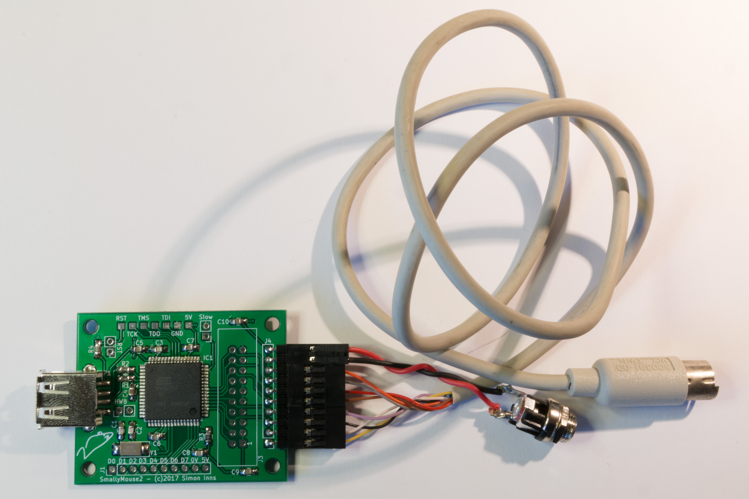
A development board fitted with all available interfaces is shown in the following picture (please note that the JTAG header is only required for development and debug functionality and should not be fitted to general purpose boards):
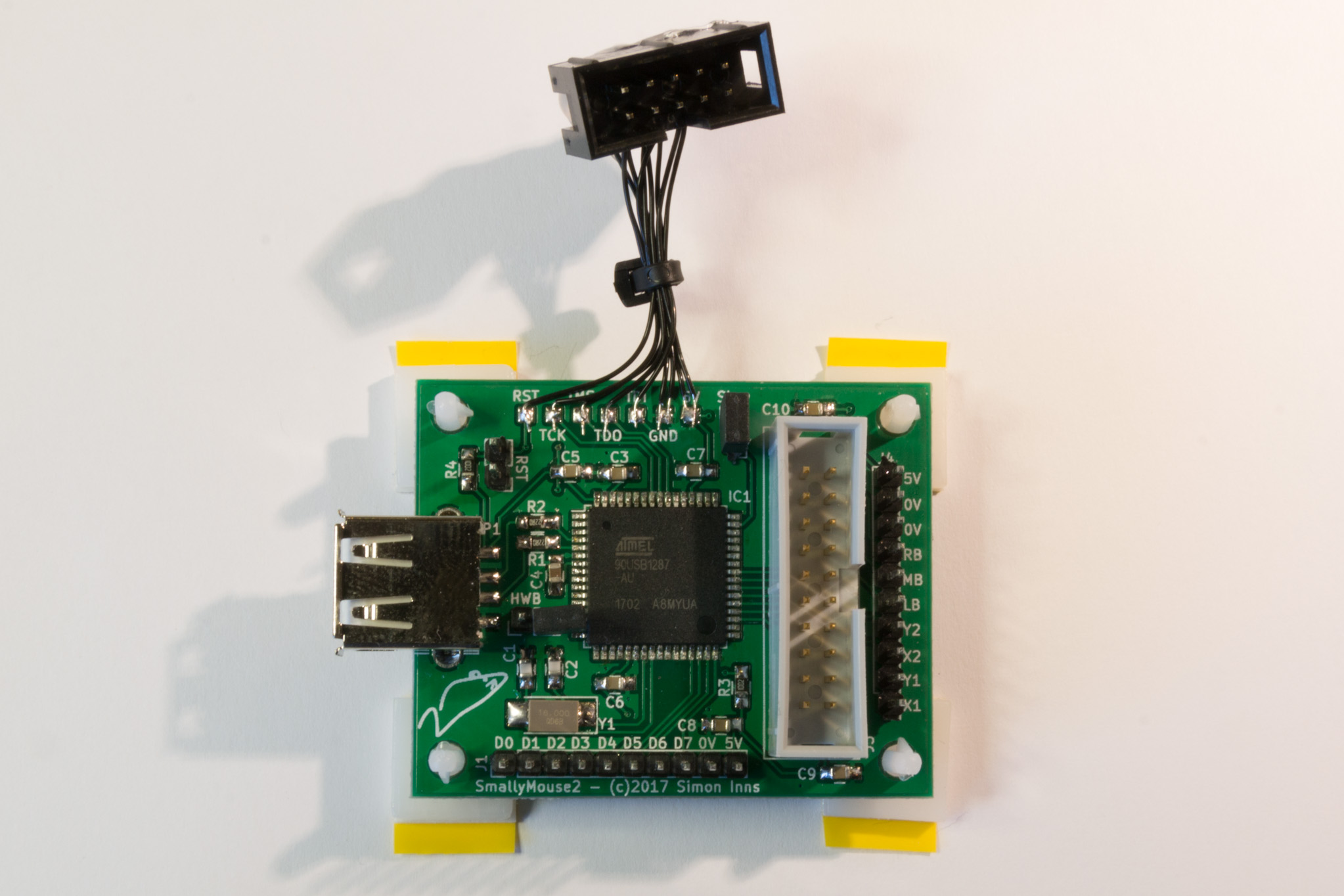
SmallyMouse2 with JTAG
USB
The USB interface can act in both USB host and USB device mode. When acting as a USB device (i.e. for bootloader programming) the board should not be externally powered (SmallyMouse2 will take power from the host device, so no other power supply should be used). When acting as a USB device it is recommended that all other interfaces are disconnected.
In USB host mode SmallyMouse2 can be connected to any USB 1.0 or 2.0 compatible mouse that uses the USB HID protocol. Note that the USB host mode support is only limited by the firmware; the USB host interface can also be used to support other USB devices (such as keyboards and non-standard mice) provided appropriate firmware support is added.
The USB interface provides a female USB A type connector. For use as a USB device (for example, when programming via the bootloader) a USB A-A style cable is required. In host mode the male USB A connector of the device plugs directly into the available connector.
JTAG
The JTAG interface is used for direct programming of the AVR microcontroller and is useful for either development work (where the USB bootloader is inconvenient) or board recovery in the unlikely event that the USB bootloader is corrupted or unavailable.
Since the JTAG header is optional (it is not necessary for general use) the interface is provided by 7 solder pads along the top-edge of the PCB. To use the JTAG header you will need to solder an appropriate 2×10 pin-header via wires connected to the available pads in accordance to the pinout of your programmer.
BBC Micro User-Port (AMX Mouse)
The BBC Micro User-Port interface is a 20 pin IDC connector (2×10) as used by the Acorn range of 8-bit computers (BBC Micro Model A and B, BBC Master 128, etc.). This interface allows SmallyMouse2 to be connected to the Acorn computer using a straight 20 wire ribbon cable with appropriate IDC connectors.
The pinout of the interface follows the AMX mouse standard and is compatible with all AMX software as well as the Acorn VFS implementation (used in the BBC Domesday project). The interface also provides power to the SmallyMouse2 board via the host machine, so no external power supply is required.
This interface is optional and can be left unpopulated if Acorn user-port support is not required.
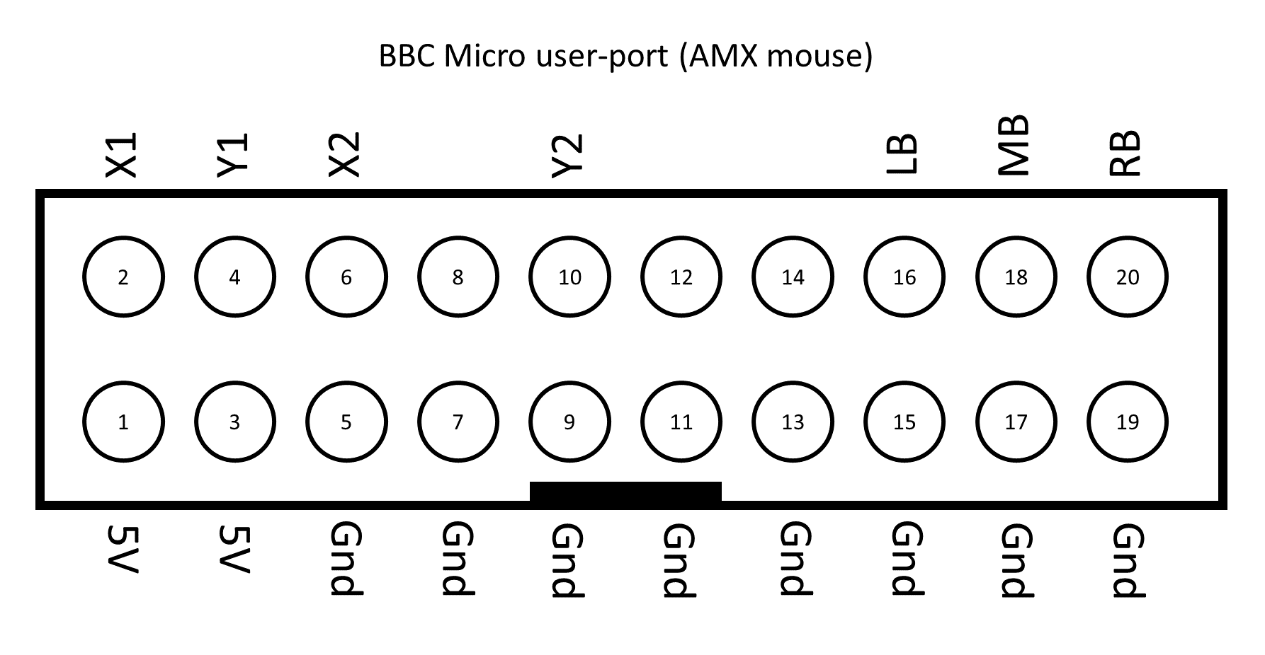
SmallyMouse2 Acorn user-port pinout
Generic quadrature mouse
The generic quadrature mouse interface is provided by a 10 pin SIL header. 4 pins are used for quadrature output to the retro computer, 3 pins are used for mouse button output and 3 pins are used for power input.
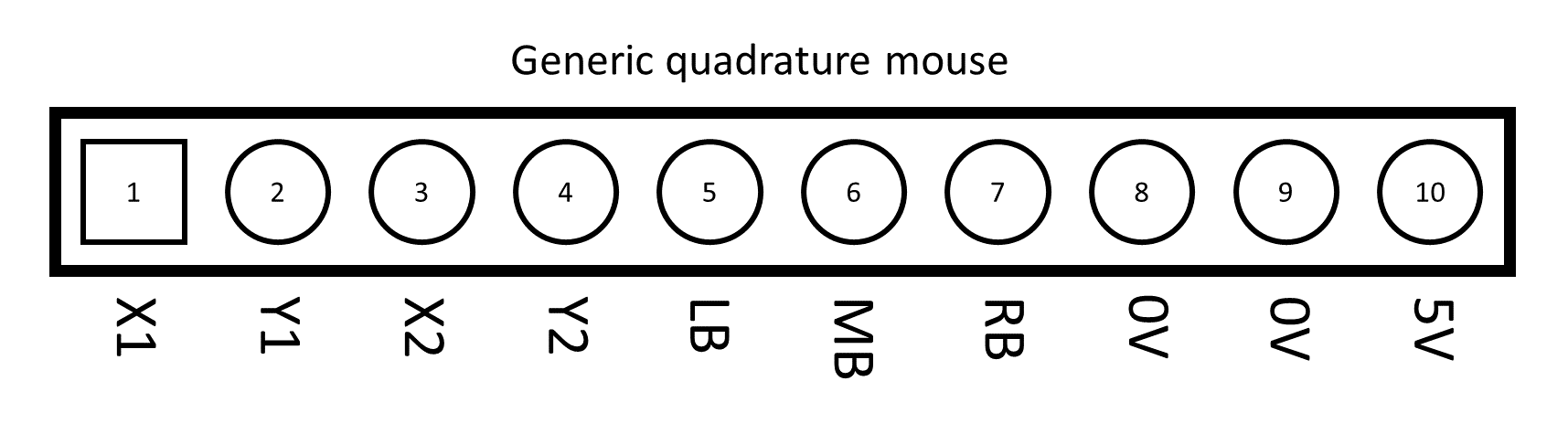
Generic mouse header
For the quadrature output each direction (X or Y) uses 2 pins marked X1/X2 and Y1/Y2. There is no standard for such pins on retro computers and they are sometimes called Xdir/Xref etc. If you are creating a cable for a retro machine then the mouse pointer movement will be inverted if the pins are connected in the wrong order; simply swapping the pins will correct the direction. It is possible to correct the mouse movement direction in software however this is not recommended as it will make the device incompatible with other cables.
Most retro computers expect either two or three button mice. If your computer supports only 2 buttons then the middle-button (MB) signal should be left unconnected.
SmallyMouse2 is designed to be powered from the retro computer where appropriate power is available. To correctly power SmallyMouse2 ensure that both the 5V and 0V (ground) pins are connected.
Care should be taken to ensure the retro computer can supply the required voltage and current. Typically, SmallyMouse2 requires 5 volts (+- 0.1V) and 180mA current (including the USB mouse). If you experience unreliable USB connectivity (i.e. the USB mouse either does not connect, or disconnects intermittently) check the power supply to the board. USB is more sensitive to incorrect power than PS/2 based solutions.
If the host retro computer cannot supply the required power, it is possible to power the SmallyMouse2 board externally. In this case one of the 0V pins should be connected to the retro computer (there must be a ‘common’ ground between SmallyMouse2 and the computer), the other 0V and the 5V pins can then be connected to an external power source. Any external source should be regulated to exactly 5 volts (as there is no regulation provided by SmallyMouse2). Alternatively, it is also possible to use a DC-DC converter (for example a charge-pump circuit) to bring the retro computer supply to the correct values for SmallyMouse2 by placing the converter in-line with the mouse interface.
An externally powered configuration is shown in the following picture (the board is populated and configured for connection to an Acorn Archimedes A400 using an external power supply connected via a DC jack):
SmallyMouse2 with an Acorn A400 cable and DC jack
Note that the SmallyMouse2 board should be powered only from a single source. If a 5V external supply is connected to the board, the host retro machine should not be connected to the 5V pin simultaneously.
Expansion header
The 10-pin expansion header is a general-purpose interface for custom extensions to SmallyMouse2 and allows for non-standard retro computer interfaces. The expansion header provides 8 general purpose IO pins and two power pins (that can be used for supplying power to add-on boards or as a power input) via a 10-pin SIL header (optional).
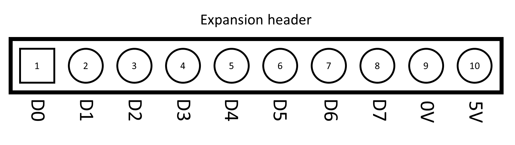
Expansion header
The expansion header also provides access to the serial UART and I2C features of the AVR microcontroller. The standard firmware provides a serial debug console via the UART. This console is useful for debugging information and provides information about the status of the USB device (device connected, enumeration, etc.). The serial console can be accessed by connecting a USB to serial converter (such as the Arduino USB2Serial board) to the expansion header; only 2 wires are required, Tx (pin 4) and 0Vs (pin 9). The Tx output from the AVR should be connected to the Rx input of the serial adapter. Serial output is 9600 8N1.
Note: For firmware release V1.2 and above the D7 pin is used for a DPI divider header (the header is placed over D7 and 0V to turn on the feature). See the section below about mice with high DPI.
Board links
SmallyMouse2 has 3 board links that can either be left unconnected or made accessible using 2 pin headers and appropriate jumpers. The link marked ‘Slow’ is used to configure the quadrature rate limitation feature. When SmallyMouse2 is used with slower retro machines (especially 8-bit), fitting a jumper to the link will configure the software to limit the maximum speed of the quadrature output (this prevents the host ‘missing’ quick mouse movements due to the limited update speed of VIA chips in such machines).
The two links marked RST and HWB provide access to the reset and hardware bootloader pins of the AVR and are not required for general use. Placing a jumper on either header will make the corresponding signal active to the AVR. These links are used for programming the AVR via the USB bootloader and should be left unconnected for normal use; please see the firmware programming section below for more details.
Firmware
Overview
The SmallyMouse2 firmware functions by using the LUFA USB stack to communicate and control an attached USB mouse device using the USB HID protocol. The USB mouse periodically sends position update reports to the host (at a rate of between 100-125 reports a second when the mouse is moving; the actual update speed depends on the implementation of the mouse). This style of updating generates problems for quadrature emulation since, in a quadrature mouse, the output would be a constant flow of information with the frequency of the pulses indicating how far the mouse has moved.
SmallyMouse2 emulates the quadrature output using the AVR’s timers (one timer for X and another for Y) – and sends the quadrature at a variable rate depending on how fast the mouse is moving. The quadrature output is timed so the device can send as much of the movement information as possible before another USB report is received.
Quadrature emulation
The output of a quadrature mouse has 4 phases (hence the name) and the speed of the phases are dependent on the mechanical encoders present in the mouse. Modern USB mice no longer use mechanical encoders so the output is digital. A modern USB mouse sends continuous reports stating how far the mouse has moved in both the X and Y direction (since the last report).
The SmallyMouse2 firmware emulates the analogue nature of the quadrature output by using variable timers that control the time between phases. For each unit of reported movement (from the USB report) the firmware advances the appropriate axis by one phase. This has the effect of providing a 4:1 reduction in the overall output speed without the loss of any ‘information’ about movement. If a USB mouse reports at a rate of 100 reports per second at the maximum movement speed (127 movement units per report), SmallyMouse2 is receiving 12,700 movement unit updates per second. This results in a quadrature output rate of 3175 Hz. Due to variations in USB mouse report frequency (and limitations of the AVR’s timer resolution) SmallyMouse2 is written to support a maximum quadrature frequency of about 3900 Hz – this is more than sufficient to provide lag-free movement.
Limiting the quadrature rate
With 8-bit retro computers it was possible to move the mouse faster than the host computer could detect – this would cause spurious updates with the mouse pointer seeming to bounce around the display. SmallyMouse2 contains a rate limiting algorithm that prevents the device from overrunning the host computer. Two definitions in the firmware control this, namely Q_RATELIMIT and Q_BUFFERLIMIT. The rate limit sets the maximum frequency of the quadrature output generated by SmallyMouse2 and is specified in Hertz (i.e. the number of quadrature signals per second). This prevents the device from outputting faster than the 8-bit host can count. Since there is only a limited time between USB reports, any extra position updates that cannot be sent to the host will be lost. The buffer limit parameter specifies how much overrun should be allowed before updates are disregarded. By altering these two parameters it is possible to tune the quadrature output for a specific computer. By default, the firmware provides a ‘safe’ value that should work with a wide-range of machines.
The Q_RATELIMIT is only applied to the output when the ‘slow’ configuration header is shorted (i.e. a jumper is placed on the 2 pin header). The Q_BUFFERLIMIT is always applied; however, this should have no effect if the slow configuration header is open (as the normal output rate should allow the output to keep up with the USB reports).
Using with high DPI USB mice
Some USB mice have extremely high DPI and can cause SmallyMouse2 to output mouse movement too fast. As of firmware V1.2 you can place a jumper between D7 and 0V on the expansion header to turn on the DPI divider feature. If turned on, SmallyMouse2 will divide the incoming USB mouse movements by 2 to decrease the rate at which the mouse moves. This can be combined with the quadrature limiting feature described above.
USB debugging
For development or troubleshooting SmallyMouse2 provides a serial debug output that can be used to monitor the status of the USB interface. This output is available on the expansion header (see the expansion header section above for details).
The expansion header D0 pin also outputs a pulse every time a USB report is processed (the pin is raised at the start of processing and lowered at the end). This allows monitoring of the rate at which USB reports are received (useful for debugging).
Firmware programming via USB
When the SmallyMouse2 board is first made the AT90USB1287 will automatically power-up into the Atmel FLIP DFU bootloader. In this mode the microcontroller can be programmed using the USB bootloader programming utilities published by Atmel (ensure that you install the USB drivers for the application too!). In addition, Atmel Studio is also compatible with the bootloader and will recognised SmallyMouse2 as a programming device.
For initial programming SmallyMouse2 should be connected to the host computer using a USB A to A cable. No other connections should be made to the board and no external power is required.
After initial programming SmallyMouse2 will configure the USB port in host mode and the bootloader will not activate by default. Further programming requires use of the RST and HWB headers on the SmallyMouse2 board (these headers can be omitted for production runs where subsequent programming is not required). To overwrite the firmware jumper connectors should be placed on both the RST and HWB links before connecting the board to the host computer via USB. Once connected via USB the RST jumper should be removed (leaving only the HWB jumper in place). This will cause SmallyMouse2 to initialise the bootloader ready for programming. Once programming is complete SmallyMouse2 should be disconnected from USB and the HWB jumper should be removed.
Example cables
Overview
SmallyMouse2 was designed to provide USB mouse connectivity to the widest possible range of retro machines and it is expected that many cable variations will be made available. As more verified cable designs are made available they will be added to this section.
Acorn BBC Model B and Master 128
The connection cable for the BBC Micro and Master range of 8-bit connectors is a direct 20 pin IDC to IDC ribbon cable. Both the BBC Model B and the Master 128 have been tested successfully with release v1.1 of the SmallyMouse2 firmware.
Acorn Archimedes A400 and RISC PC range
The following pinout is used to connect SmallyMouse2 to the Acorn Archimedes A400 and RISC PC range of computers:
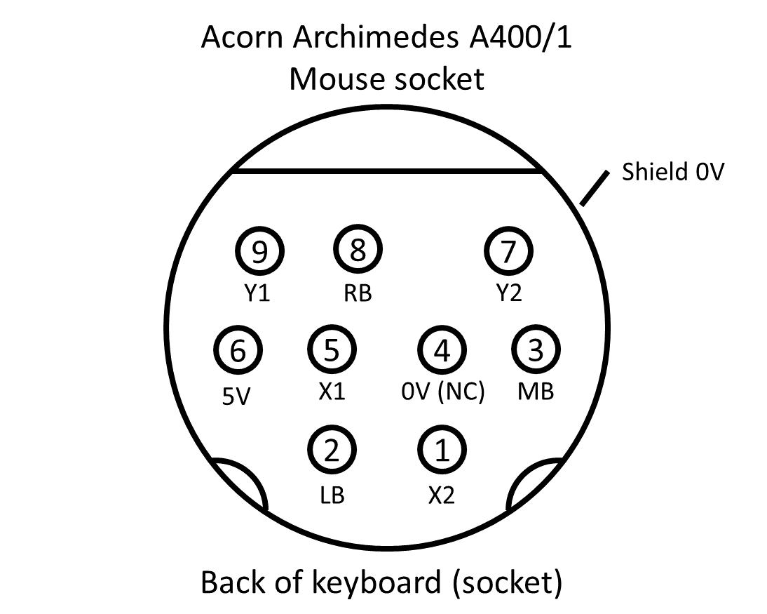
Acorn Archimedes A400 mouse cable pinout (host-powered)
The Acorn Archimedes A440/1 computer and the Acorn RISC PC 600 has been tested successfully with release v1.1 of the SmallyMouse2 firmware.
Commodore Amiga
The following pinout is used to connect SmallyMouse2 to the Commodore Amiga range of computers:
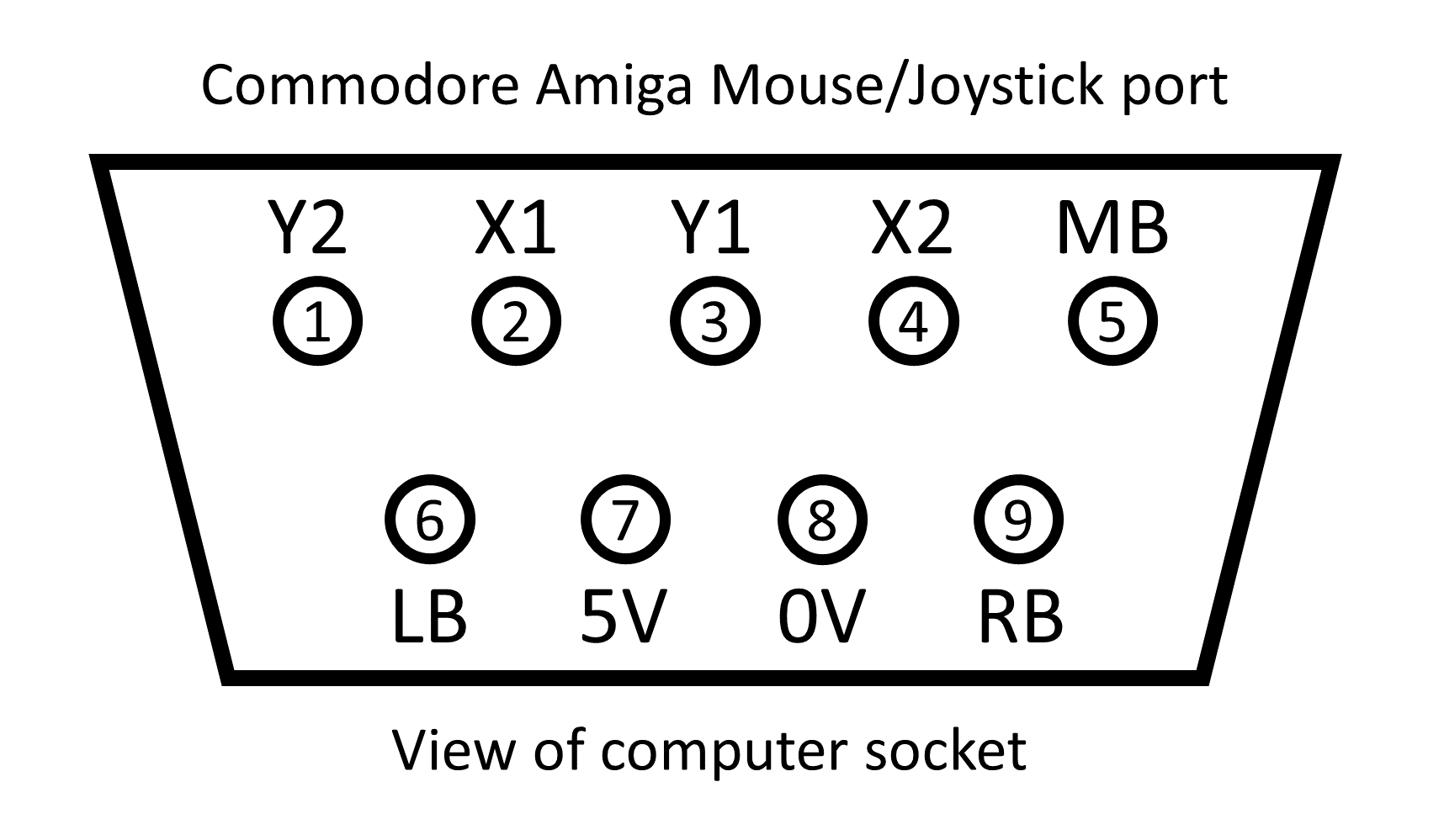
Commodore Amiga mouse cable pinout (host-powered)
The Commodore Amiga A600 has been successfully tested with release v1.1 of the SmallyMouse2 firmware (testing and pinout kindly provided by Bas of BetaGamma Computing).
Note: The rated maximum output of the Amiga mouse/joystick port is only 50mA; so technically you will need to externally power the SmallyMouse2 board (leaving pin 7 from the port disconnected); however testing shows that the port is generally capable of supplying enough power (previous PS/2 based adapters have been used with Amigas and these will have a power draw similar to the SmallyMouse2 board).
Atari ST
The following pinout is used to connect SmallyMouse2 to the Atari ST range of computers:
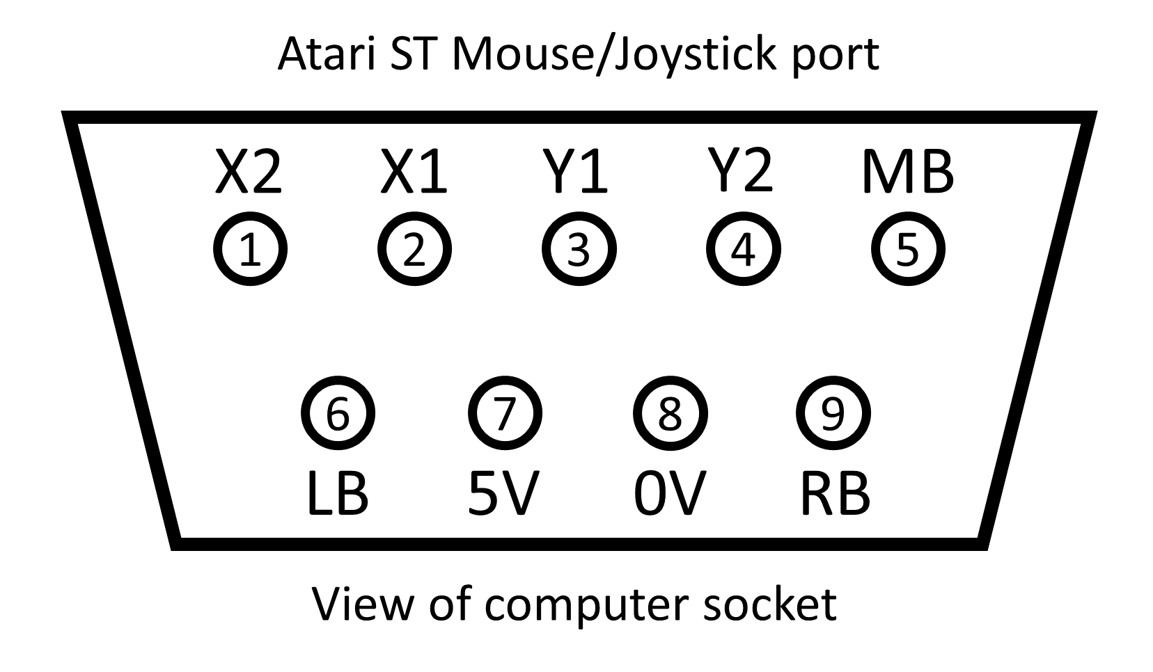
Atari ST mouse cable pinout (host-powered)
The Atari 520 ST has been successfully tested with release v1.1 of the SmallyMouse2 firmware (testing and pinout kindly provided by Bas of BetaGamma Computing).
Note: The power output from the Atari 520ST mouse/joystick port was measured at only 4.5V (on the machine used for testing). This can cause unreliable USB connectivity. An external 5V power supply is recommended (leaving pin 7 from the port disconnected).
SmallyMouse2 Logo
The SmallyMouse2 logo is a monochrome rendering of a mouse with the tail representing the number 2. The logo was drawn in Adobe Illustrator and can be downloaded from the GitHub repository.

SmallyMouse2 Logo
Conclusions
SmallyMouse2 was designed due to the encouraging response and feedback from the original project. There seems to be a big demand for an interface to allow retro computers to use even the most modern mice. The project has been released as open-source and open-hardware to allow anyone to make the device either for personal use or for resale. All such activities are positively encouraged and even commercial sale is allowed by the licensing (however anyone intending on such activities should ensure they understand the share-alike nature of both the GPL and CC licenses intended to ensure the project remains open to all).
If you liked this project or came to the site for firmware updates or other information, please consider leaving a PayPal donation to help fund this and future projects! As a non-commercial open-source, open-hardware project only your donations to this site fund development.
Files for download
All project files are available from the GitHub repository:
Please note that any firmware enhancements will be made available via GitHub in the releases section of the project.
Where can I buy one?
SmallyMouse is an open-source, open-hardware project. Everything you need to make your own board is available from the GitHub repository. WaitingForFriday.com doesn’t supply ready-made boards or kits (just the actual work of designing and development!) – if you’d like to buy a SmallyMouse2 then you are welcome to try the following resources (note: these resources are not associated, supported or endorsed by WaitingForFriday.com and are provided for your convenience):
BetaGamma Computing in the UK is making and selling completed boards. Please see their Facebook group page for details:
BetaGamma Computing (Facebook)
The renown Acorn shop CJE Micros is also producing completed boards in the UK. More information is available on their web-shop:
User [dnotq] has posted the board design on OSH Park (a service where you can order the bare PCB for making your own board):
If you know of any other sources for SmallyMouse2 please post in the comments and I will add them to this list.
This is a great project, but would it be possible to add USB keyboard support for retro computers as well?
The advantage of quadrature mice is that, although the connectors are not standard, the output to the retro computer is, therefore it’s possible to make a universal adapter such as SmallyMouse2.
Keyboards are another issue entirely. Whilst the USB hardware of SmallyMouse2 is quite capable of interfacing to a USB keyboard; the real issue is the interface to the retro computer. They all use different keyboard layouts and different interfaces. Furthermore, to support a ‘scanned matrix’ style of keyboard (common in many machines) you need something like a crosspoint switch IC to emulate the matrix.
That’s the long answer, the short one is ‘not really practical’ 🙂
Yes, I can see how that would complicate things.
Perhaps, being an open-source project, different people could get together and work on a version for their own platform. Would that be an option?
Personally, I’m interested in a USB mouse/keyboard solution for the Atari ST. There are USB keyboard/mice options available which rely on an Arduino and a similar project which relies on a Raspberry Pi.
There are minor problems like USB hubs not working (only possible to use a wireless mouse/keyboard combination, or just one or the other if wired) and I’m also a little apprehensive using what is essentially a small computer needing to boot and with SD memory cards that can corrupt and crash the system.
Perhaps the people who have designed those systems could look into your hardware and use it to further develop the keyboard part using their know-how?
You (and anyone else) are more than welcome to use and build upon the project – that’s the beauty of open designs 🙂 I do intend to look into the issue of keyboard support myself (no fixed time line though at the moment).
I’m not sure about LUFA support for hubs (LUFA is the underlying USB library I’m using) – If I get some time I’ll set up a test and find out what happens. SmallyMouse2 supports serial debugging; so it’s a good platform for such experimentation.
What are the consequences of the lack of amps and lack of voltage for the Amiga and Atari ST? Should the interface respond at all, should it work occasionally or should it be completely unresponsive?
I’ve made cables for both computers – using the 5V power from the computers as I forgot about the amps/voltage – and when I hook a mouse up to the SM2, it doesn’t do a thing. I know the mouse and interface are fine as all works perfectly with a RISC PC. I’ve measured the voltage across the 5V-0V pins, and the electrons are flowing.
The computers work fine with their usual mice, so either my cables are wrong (more than likely), or there’s insufficient amps/volts.
Both the Amiga and ST do not provide enough rated current to power a modern USB mouse according to their documentation; however the Amiga seems to function anyway and I have had inconclusive reports about the ST. Both should work fine if you externally power the SmallyMouse2 board. Having said that; these machines are old and the PSU in yours may not be providing 5Vs (most USB mice require 5Vs… not 4.5, or 4.8 or 4.9 🙂 )
Pretty much all the other mouse adapters out there (primarily PS/2 based ones) are all running overrated – so if any other adapter works, SmallyMouse2 will also. The only real difference is that, as an open-hardware project, it doesn’t harm my “sales” if I state that. The original mice are probably not a good test though; typically they only contain one low-power IC, so will draw less than 50mAs and are not sensitive to the voltage level.
If there isn’t enough power; typically the USB mouse will not enumerate; and therefore won’t function.
Ah, that explains it then – many thanks for the reply.
Daft question time: should I rejig my cables to connect both the 5V and 0V pins to an external PSU, or will changing just the 5V pin be sufficient? (It’s a long time since I did anything to do with electronics.)
There are two 0V/GND pins on the header. This is so you can connect one 0V to the host and then the other 0V (and the 5V) to the external power supply. Everything needs a common ground, but there should only be one source of power.
I’m still struggling to get my SM2 to work properly with an Amiga 1200. I can move the mouse around and click on the left mouse button without problem, but the right mouse button is unresponsive. As I understand it, a button press is registered if the relevant pin is grounded to 0V.
I have noticed that there is a difference in voltage when the left button is pressed compared to when I press the one on the right. Pressing the left causes the voltage to decrease to 0.03V, whereas the right doesn’t go lower than 0.3V. Testing the middle button also shows 0.3V.
If I short the RB pin to the 0V pin on the underside of the interface, the computer responds as if I’d physically pressed the button. To me this looks like 0.3V isn’t a low enough voltage for my Amiga to register that as a button press.
Any assistance would be appreciated.
I’ve done a bit more experimentation: if I disconnect the interface from my Amiga, the voltage *does* drop to 0V when the right mouse button is pressed. If I connect it again, the voltage stays at around 0.3V as before.
Using the same setup for an Atari ST (with X2/Y2 swapped over) works fine, so it’s obviously something odd with my Amiga. I’ve tried different mice, cables and PSUs, all to no avail.
Hello Simon,
first of all: Thank you for this great project! 🙂 I’ve ordered some PCBs to get some modern mices to work with my Amiga and Atari computers to work hopefully some day. I’ve also soldered all necessary parts on it. It was fun to build it.
Unfortunately I’m not getting any further. When I set a jumper on HWB and RST and release the RST connection after connecting SmallyMouse2 to my computer with the USB cable I’m not getting any new USB device to set up or install drivers for. I’ve tried it on Windows 10 and also on Linux (lsusb doesn’t show any new devices).
I have checked several times if there is an unwanted connection between two attached contacts of the 90USB1287-AU but everything seems to be fine. Checking GND and +5V is also OK, I get a voltage of 5V.
Of course there is a possibility one of the parts is broken but to you have any other idea what I should check? Is there probably the bootloader of my microcontroller missing?
With a new AVR chip it shouldn’t even be necessary to jumper the HWB and RST – unprogrammed, it should just default to the bootloader. I have seen in the past that some chips (sourced from questionable places like aliexpress) do not have a bootloader (most likely because they are fake/seconds). If you are sure the hardware is correct then you can try hooking up a programmer to the programming pads on the PCB and flashing the bootloader.
Thank you for the answer. 🙂 But: Oh dear!
I bought the 90USB1287 chips on eBay and they came directly from China. I hope they are no fakes at least and there is “only” the bootloader missing. But let’s be honest: I’m not an electronics geek and I don’t really know what to do now. I don’t want to bother you too much but do you have a good hint for me what I should try/do to see if I can write a bootloader on the chip or how I can transfer the SmallyMouse2 firmware to it?
I’ve soldered Dupont cables to the JTAG pads and bought two kinds of programmers. I searched for an AVR programmer which supports the 90USB1287 as device and which is compatible with the AtmelStudio 7. They have both an ISP interface. The first one is a STK500 compatible device, the second one is called “Diamex AVR USB ISP Programmer stick”. Both react when I change/read some of the settings in the AtmelStudio. Unfortunately reading the device properties/signature or the settings for the fuses leads always to the error:
“Failed to enter programming mode. ispEnterProgMode: Error status received: Got 0xc0, expected 0x00 (Command has failed to execute on the tool)
Unable to enter programming mode. Verify device selection, interface settings, target power, security bit, and connections to the target device.”
Now I’m not sure if this is just a problem with some incorrect settings or an indication that I’Ve got some fake chips. Do I have to change something in the source code perhaps when trying to programm the device via JTAG?
I’d suggest you buy at least one chip from a real electronics distributor and try that. If you get good results, you know the other chips are bad; if not – you have a hardware issue of some type.
Hi. I have a SmallyMouse 2 board attached to the User port on a BBC Master. It works fine with the MAX sideways ROM but the AMX software has issues if I move the mouse above a (fairly low) speed. I was going to try to update the board and try tweaking the parameters to see if I could resolve that. However, I’m having issues getting the board to be recognised when I connect it to my PC via USB A-A cable: my PC doesn’t detect anything. Can I confirm a couple of things?
First, how should the USB A-A cable be wired? Is it straight through (pin 1-1, 2-2, etc.) or should they be crossed over (1-4, 2-3, etc.)? I’ve found both suggestions on the web, presumably because this cable isn’t standard. A cable I have (for programming old outdoor wireless access points!) has straight through and that isn’t working: I wanted to check before I break that up and cross it over.
Secondly, I presume the board will power from this USB interface during this and won’t need a separate supply?
Thanks for any help!
I pretty sure the A-A cable is straight-through, I’ve never made one though since I just grabbed one from ebay. If the programming USB device isn’t showing up it’s most likely because you are not putting the device into programming mode. If you simply plug it into a PC nothing will happen (instructions are above). When programming only the USB cable is required (also covered above). Be aware that, if you see issues with more than one USB mouse, it could be the 6522 VIA chip inside the BBC at fault; it might be worth trying another one.
Thanks for the reply. I believe I’m doing the RST + HWB jumpering correctly on boot up, but I might not be: there are no pins on the board I have, so I’m just looping some wire through the two holes and pulling it tight, but I’ll check that more carefully (the board also doesn’t quite match the images you have on your website, so I’m not sure if it’s been adjusted in some way)..
Regarding the 6522 VIA, I have a Turbo SPI board with MMFS ROM running perfectly fine on the same port. Would that test all the same things? I don’t have another BBC or mouse to check things, unfortunately.
Hi, i recently bought an usb mouse adapter for my MEGA STE but it did not work properly: ok both buttons; vertical cursor movement was right but not its horizontal movement (it always fell to the left). Luckily I found very useful information in this web. I’ve tried to decrease Q_RATELIMIT and Q_BUFFERLIMIT. The first tried Q_RATELIMIT=400 and Q_BUFFERLIMIT=200. The mouse got all directions movement but a little bit spurious. Then, I tried to leave Q_BUFFERLIMIT=300 (default value) and change Q_RATELIMIT=450. This works for me. I have to move the mouse a little bit slow than usual in horizontal direction but i can work again with my ATARI. I’ve tired to change the DPI_DIVIDER to 3 but then i couldn’t write the program in the adaptor chip (report error when i tried to write).
I hope this information was useful to everyone
HIHi, and thanks for this project. It should prove usefull for my vintage coputer collection. I was wondering, however, is it possible to run the firmware on the AT90USB647, or is the code to large for this chip?
The code should fit easily; I’ve never tested it on that chip though – if you are successful please report back (or use the issues tracker on the project github).
Thanks for the reply. I am currently re-mixing the board into a form factor that I can have a DB9 on it and plug directly into the A500 mouse port. I am adding a jumper to indicate Amiga or Atari, and adjusting the code to make appropriate changes to the pinout, so the same board will work on either system. I plan to make all available and open-source, as required by the licensing. Time will tell, as I have a bunch of projects on the go, but hopefully I will have the first boards to play with in the comming weeks, and will post my results.
Hi,
First of all thanks for a great project and making it open source.
I have built one for my Amiga 500 and it is working. But I have found 2 minor problems.
When moving the mouse VERY slowly the mouse movement becomes jerky or stops. This is only a minor inconvenience as moving the mouse a little faster fixes the problem.
Also when pressing and holding the right mouse button the same thing happens but a lot worse. Once again moving the mouse faster fixes this problem. But this one is a bit of a nuisance.
I have tried setting the SLOW jumper on SS2 and different mice. With no change.
I will try using a separate 5V supply for the SS2 to see if that helps.
But in the meantime any idea as to why this is happening?
It is usable like this just a little annoying when accessing the drop down menus with the right mouse button.
Thanks again for a great project.
Make sure you compile and use the latest firmware – then retest. If the problem persists use github to raise an issue report describing the board used (if it varies from the project) and the observed issue.
I was indeed using old firmware. (Bit new to GitHub) But after flashing V1.2 the issue is still there.
Just to make sure it wasn’t a hardware problem I assembled a second SS2 and tested it. It has the same problem. So it looks like a firmware issue.
Could be my Amiga I guess, but I have no way to check this as I don’t have an Amiga mouse.
I’ll raise an issue in github.