PC Case USB LCD
Contents
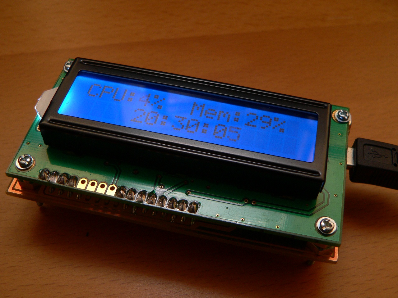
For the first version of my Open Source Framework for USB Generic HID devices based on the PIC18F and Windows I made a quick example of how to use the library using a USB interface for an LCD. Now that I’ve completed the second version of the library I thought it would be fun to enhance the LCD project into a completely self-contained LCD module which would fit in a 5.25 inch drive-bay of a PC case.
This project explains how the LCD module can be built along with PIC firmware and Windows host software written around the C# USB Generic HID library. For the example host code the CPU and memory utilisation is displayed on the LCD along with the current time. The hardware is the same size as the LCD itself and can be mounted directly behind the ATM1602B 2*16 LCD module to provide a compact host-powered LCD for many applications.
LCD Module
Hardware
The hardware design is extremely simple and can be built using the supplied PCB artwork or on a stripboard/breadboard. The circuit consists of a PIC18F2550 with a 20 Mhz resonator and the required components for the LCD screen and the USB.
The PCB artwork required to build the controller board is available in the zip files at the end of this article.
Here is the circuit schematic for the LCD controller board:
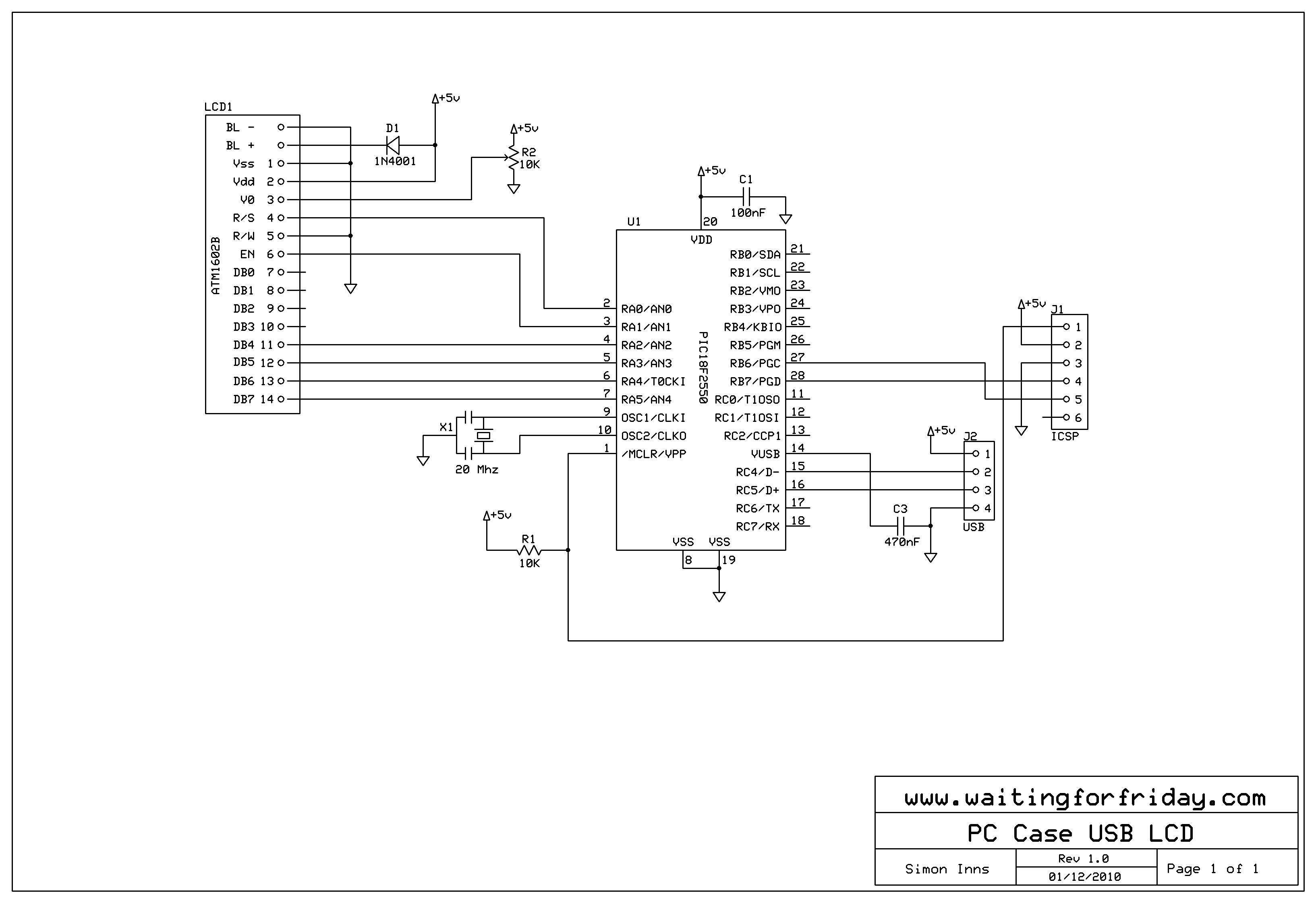
PC Case USB LCD Schematic
The circuit board uses mainly SMD devices (although you could fit through-hole devices in the same space it saves a lot of time drilling holes). Also the USB connection is provided via a SMD mini-USB connector which keeps the whole module very thin and space-efficient. Only the top copper layer is used (and there are no jump wires required) so this can be easily made with a single sided PCB. Here is a picture of the completed board:
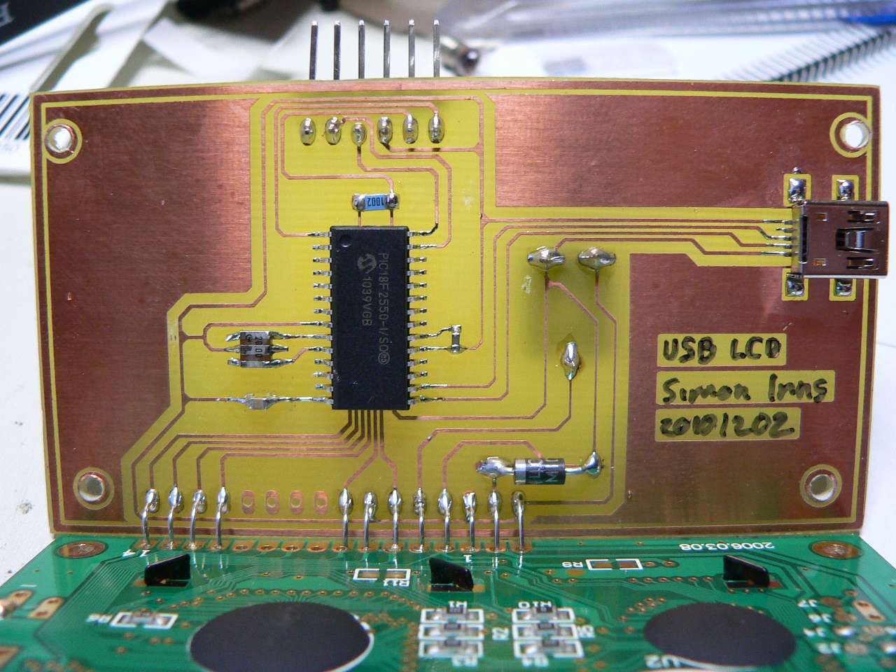
LCD Circuit
As you can see in the picture, the display is connected to the controller board using single strand wire. You simply solder the wire to the controller board then mount the LCD on top using some screws (and I used some M6 bolts to act as spacers) and then solder the wires to the LCD.
The contrast control potentiometer is mounted underneath the board to allow easy adjustment after the LCD screen has been mounted. The diode can be soldered on the top or bottom of the board; I decided to keep it on the top to make the finished module look neater.
Firmware
The firmware is based on the software available from my Open Source Framework for USB Generic HID devices based on the PIC18F and Windows (Version 2_0_0_0) and implements several USB commands allowing the host to clear the display, move the cursor, output text and write a ‘raw’ byte to the LCD display. The raw byte command allows the host to be able to send custom commands to the LCD so that you can implement things like special LCD characters without having to alter the PIC firmware (if you know a bit about the communication that is possible with the ATM1602B). Furthermore there is no reason why you could not use the same firmware to communicate with the larger versions such as the 4*16 display. I chose the 2*16 because it can fit behind a single drive-bay cover.
Windows host software
The host software is written using Visual Studio C# 2010 and has been tested with Windows 7 (although it should work fine with Vista and XP).
The host software implements the performance counters and passes the appropriate text strings to the PIC firmware. The mechanism is very simple and should be extremely flexible if you wish to implement your own display information.
In addition, version 2 of the USB HID library implements an example debugging log stream from the USB firmware to the host which is demonstrated in the host code.
Here is a screenshot of the GUI:
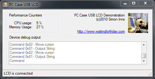
PC Case USB LCD application
As you can see from the screenshot the application monitors both the CPU and the memory usage using windows’ built in performance counters. In addition there is a debug text box which shows the live streaming debug information coming from the USB firmware (which is extremely useful for more complex firmware design and debugging).
Mounting the LCD
Along with the PCB artwork and the schematics is a cut-sheet which acts a template for cutting a standard 5.25 drive-bay cover so you can mount the display in a PC Case. Here is a picture of the display mounted in my PC:
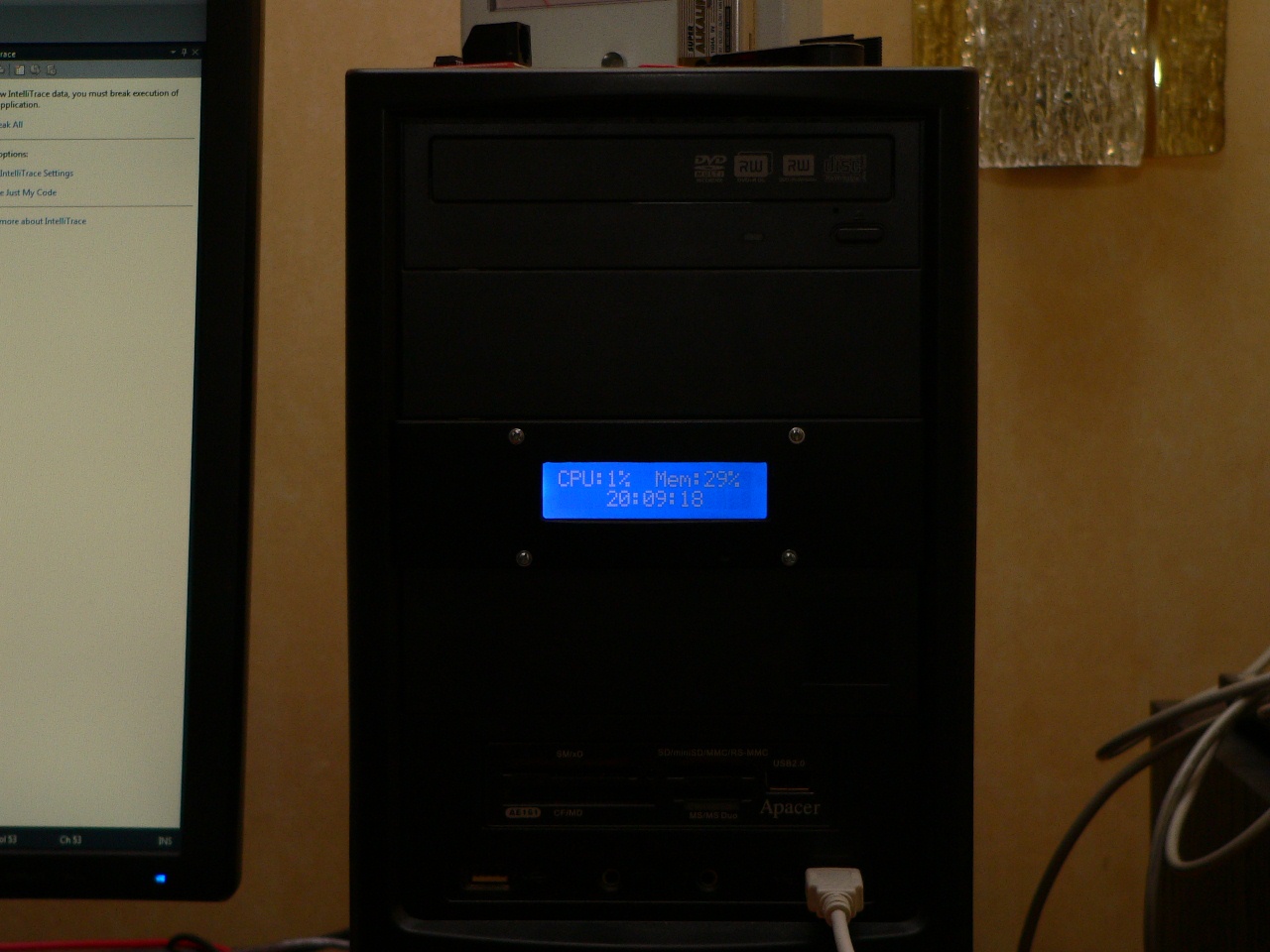
LCD in PC
Files for download
The PCB artwork and schematics in expressSCH and expressPCB format (these are freely available programs) – also includes a panel cut-sheet to help with mounting the LCD module:
PC_Case_USB_LCD_Schematic_Files
The PIC18F2550 firmware source code (for HiTech C18):
The Windows source code in Microsoft Visual Studio 2010 C#: