ToothPIC
If you regularly breadboard USB designs you’ll know that every project requires you to build the basic building block of a PIC and associated components for USB communication before continuing with your experimental design. ToothPIC is a very small PIC18F2550 board which includes the required PIC microcontroller, 20Mhz clock, USB connector and the standard passives (resistors and capacitors) to make it work.
The board is USB powered and gives access to all 28 pins of the microcontroller from the breadboard.
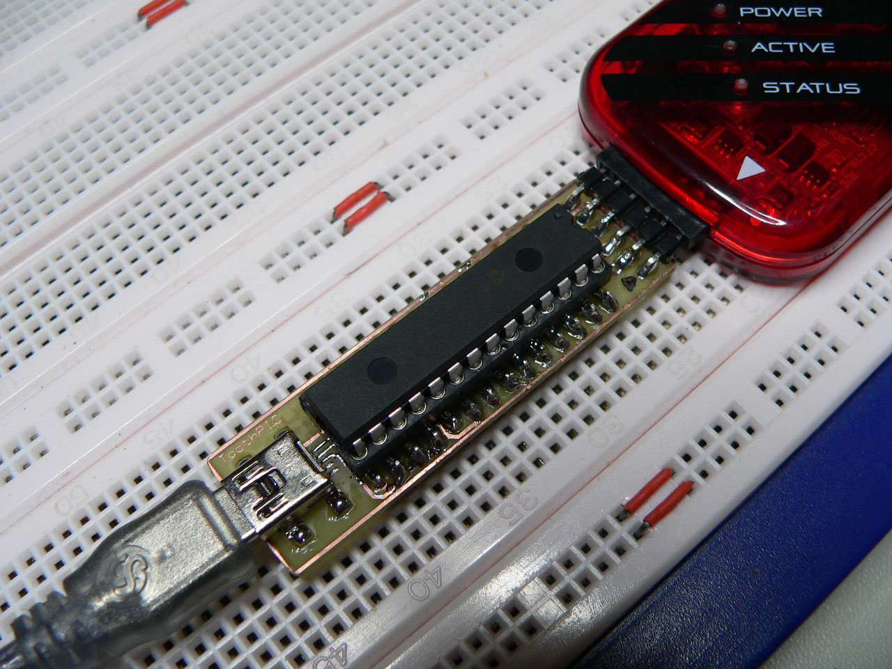
ToothPIC top
Hardware
The hardware design is very straight-forward and consists of a PIC18F2550, a mini-USB socket (SMD), a 10K resistor and two capacitors (100nF decoupling cap and a 470nF cap for the VUSB pin). A standard 6 pin header is also included to connect the board directly to a programmer such as the PICkit 3. A 20Mhz SMD resonator with built in capacitors is mounted on the underside of the board.
Here is the circuit schematic for the ToothPIC board:
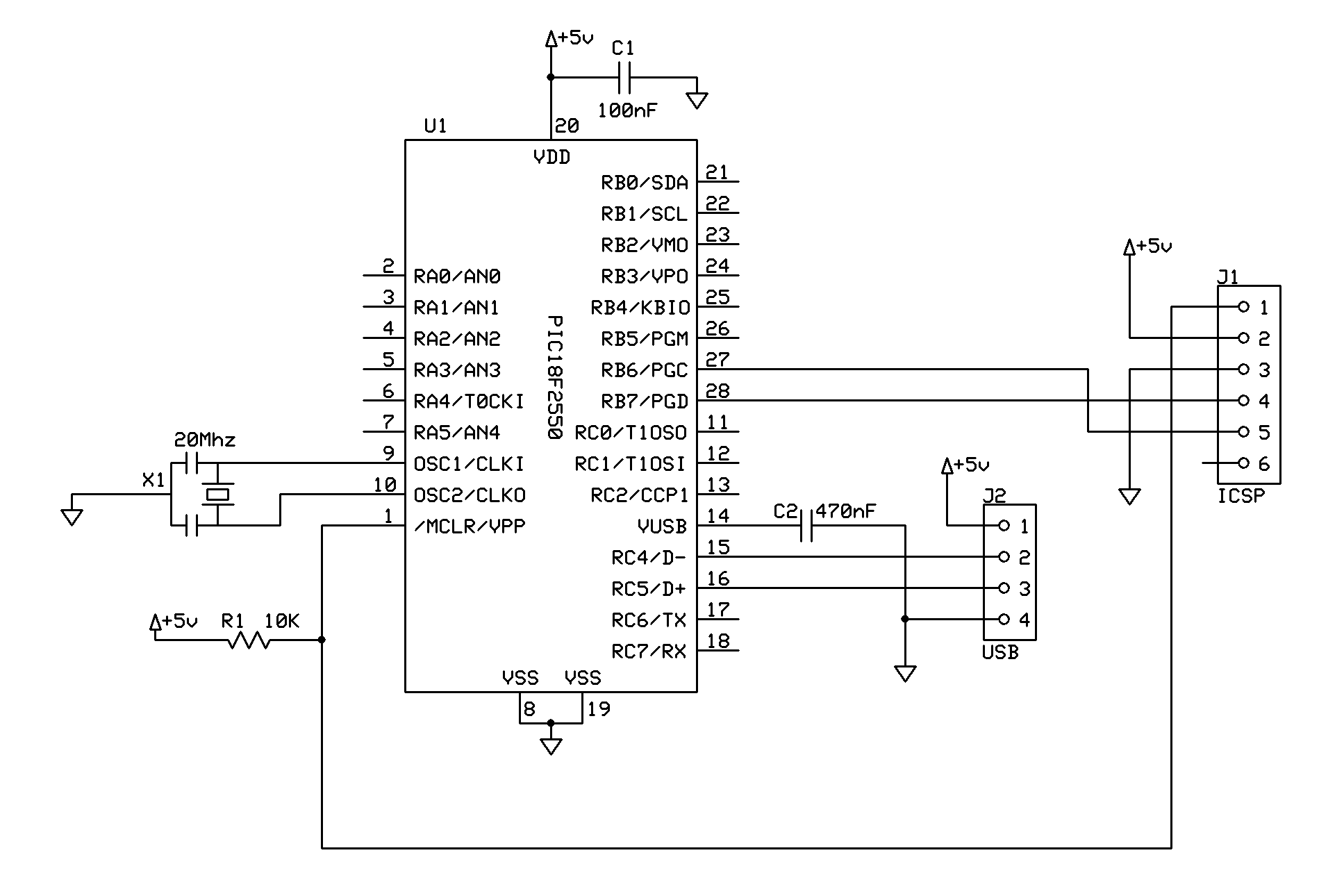
ToothPIC Schematic
On the underside of the board are 2 x 14 pin 2.54mm headers which allow you to plug the board directly into a standard experimenters breadboard:
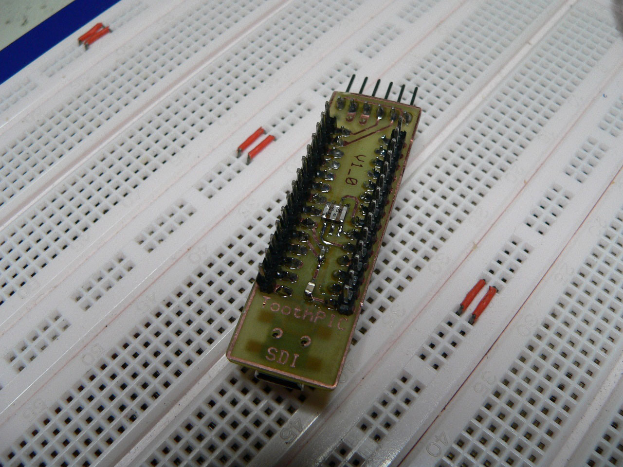
ToothPIC bottom
The IC socket (if you decide to use one) must be soldered on both the top and bottom layers of the PCB. On the top layer you can solder the IC holder by soldering the headers and pushing the solder back under the holder as you go. Test the board using a multimeter to ensure that all of the pins are connected to the top of the board once you have finished There are two ‘vias’ on pins 2 and 3 of the programming header in case you want to use a ‘straight up’ header rather than the 90 degree one I used (since you cannot solder both sides of the board with a straight header).
The PCB artwork is as follows (created in ExpressPCB) and can be downloaded below:
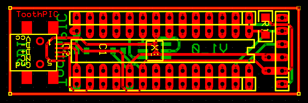
ToothPIC PCB Artwork
Files for download
The PCB artwork and schematics in expressSCH and expressPCB format (these are freely available programs):