Acorn Speech PHROM TMS6100 Emulator
Contents
This project creates a TMS6100 speech PHROM (PHrase Read Only Memory) for use with the TMS5220 Voice Synthesis Processor in an Acorn BBC Microcomputer. Whilst it’s still possible to purchase TMS5220 ICs from sites like Ebay, the TMS6100 was a mask-programmed ROM that Acorn produced specifically for their speech upgrade and is therefore difficult and expensive to source. Instead of using the original ROM, this project uses an ATmega32U2 microcontroller to both emulate the ROM and provide the original Acorn voice sample data recorded by BBC newsreader Kenneth Kendall.
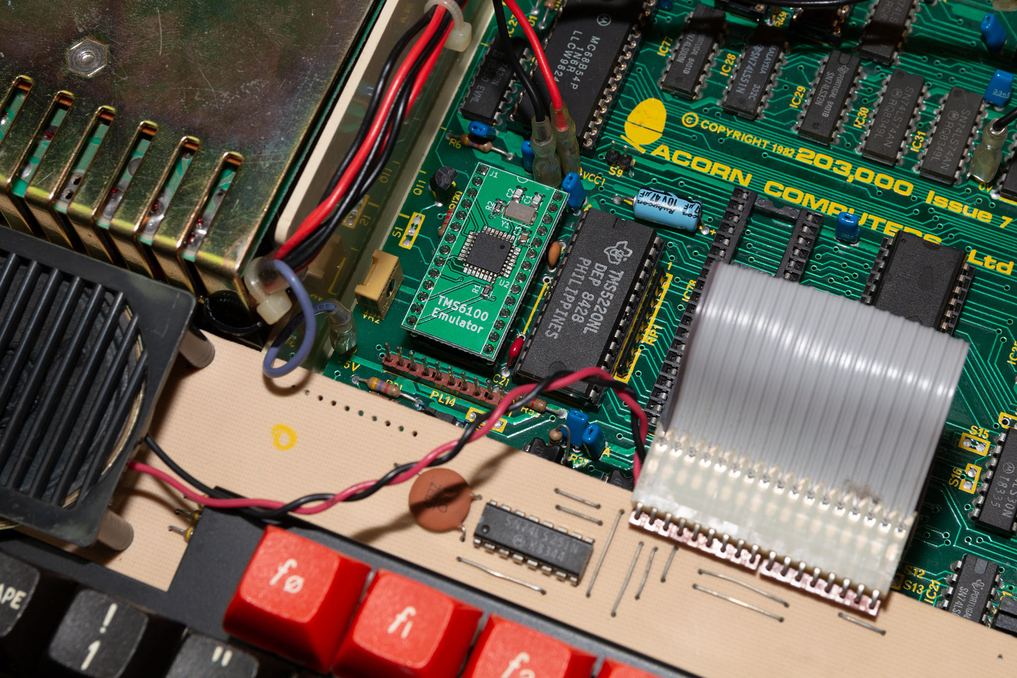
The design fits in the BBC micro’s PHROM socket and required no modifications to the BBC Micro in order to work. The board consists of only 7 components; 3 capacitors, a crystal, 2 resistors and the microcontroller.
You can hear the emulator and the TMS5220 in action in the following YouTube video:
Hardware
Schematic
The TMS6100 is an unusual ROM in that it provides a parallel address bus along with a serial data transfer (the original ROM was also capable of 4-bit parallel data transfer, however this is not used by the TMS5220 processor).
The following schematic diagram shows the TMS6100 header pins and the connections to the ATmega32U2:
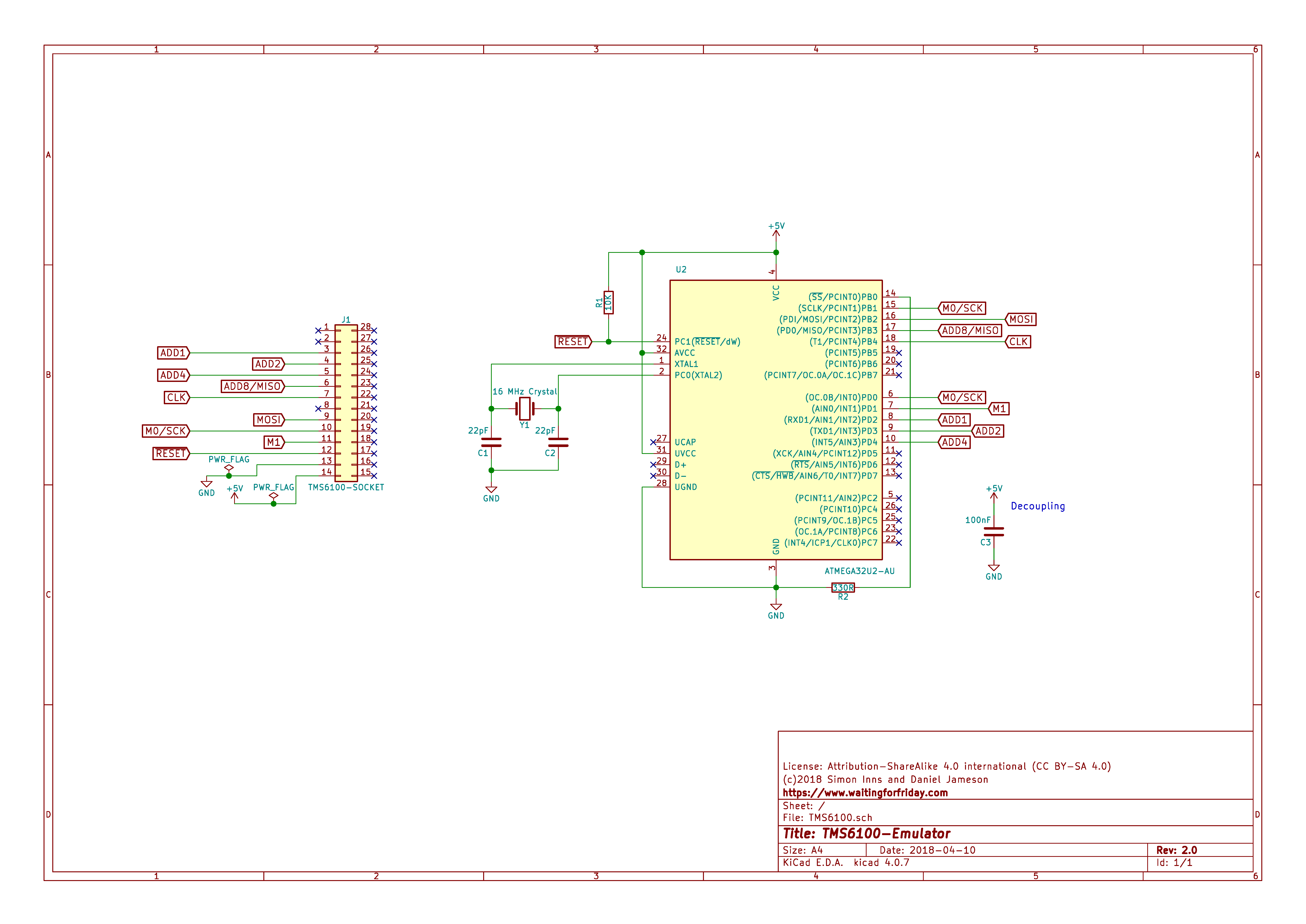
As can be seen in the schematic, there are 4 ‘ADDx’ pins that act as the address bus. ADD8 also doubles as the MISO (Master In Slave Out) SPI pin. In addition, there are two ‘command’ pins M0 and M1 that act together to tell the TMS6100 which command to execute and (in the case of M0) act as the SPI asynchronous clock for data transfer.
Due to this dual use of M0, it is connected both to the SCK (SPI clock in) of the microcontroller as well as PB1 (external interrupt 1). The hardware design uses a combination of the ATmega’s SPI peripheral (for the high-speed data transfer) and the INT1 (for M0) and INT2 (form M1) external interrupt pins (for detecting and reacting to incoming command pulses). The TMS6100 also has a clock input (CLK) which receives a clock signal from the TMS5220 to ensure the logic in the PHROM was synchronized with the processor. In this application the CLK signal is not required (as the ATmega can asynchronously react to the SPI CLK alone), however it is connected in the hardware for future use/expansion.
To allow the ATmega to be programmed (using in-circuit programming over SPI), the rest of the SPI pins and the !Reset pin are also exposed on the ‘Not Connected’ pins of the TMS6100.
The original TMS6100 was powered from a dual-supply -5V – + 5V power supply; obviously this is not suitable for use with a modern processor such as the ATmega32U2. In order to power the microcontroller the design draws positive voltage from the TM6100’s Vss pin and relies on the presence of a ground through the !CS pin (which is connected to 0V ground in the BBC Micro).
Bill of Materials
The TMS6100 requires very few components and (with the exception of the AVR chip) there are many types to choose from:
- 2x 22pF 0805 capacitors
- 1x 100nF 0805 capacitor
- 1x 10K 0805 resistor (1%)
- 1x 330R 0805 resistor (1%)
- 1x ATmega32u2-AU (TQFP-32 7x7mm with 0.8mm pitch)
- 1x 16 MHz crystal (2 pin 5.0×3.2mm – 18pf/60R such as RS components 813-6116)
- 2x 14 pin male pin headers (turned pin are best as they fit in the IC socket easier)
Programming
In order to program the AVR the TMS6100 should be placed in a breadboard. Ensure that the following connections are made:
- AVR programmer pin 1 (MISO) – TMS6100 pin 6
- AVR programmer pin 2 (Vcc) – TMS6100 pin 14
- AVR programmer pin 3 (SCK) – TMS6100 pin 10
- AVR programmer pin 4 (MOSI) – TMS6100 pin 9
- AVR programmer pin 5 (RST) – TMS6100 pin 12
- AVR programmer pin 6 (GND) – TMS6100 pin 13
You will also need to connect pins 13 and 14 to a 5V supply in order to power the AVR during programming.
PCB Design
The PCB design can be seen in the following diagram:
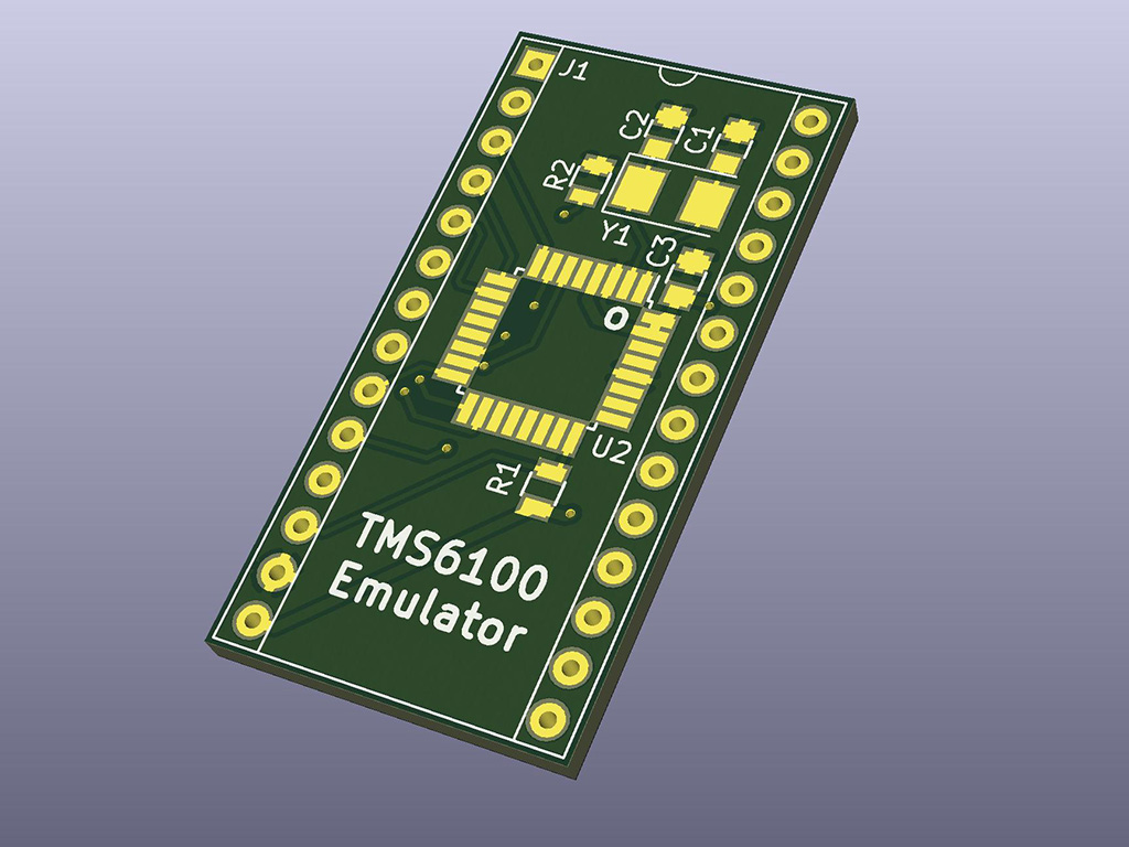
The PCB is designed to be made double-sided using a PCB fabrication service). Full KiCAD schematics and PCB design are provided at the end of this article.
Firmware
The TMS6100 provides 3 commands for the TMS5220 to use (and therefore, the host microcomputer). The commands are as follows:
- Read data
- Load Address
- Indirect Address
Note that the Indirect Address command is not used by the TMS5220 and is therefore not implemented in the emulation firmware.
The read data command has two primary forms a ‘real’ read (where the TMS6100 initiates data transfer to the TMS5220) and a ‘dummy’ read command. In order to provide a ‘real’ read the TMS6100 must have a valid address from the TMS5220. This address is sent as a 20-bit value using 5 nibbles of data sent from the processor. If the processor sends a read data command before transferring 5 nibbles of data, the TMS6100 resets into a known state (clearing any partial address nibble writes).
The BBC microcomputer causes the TMS5220 to send 16 ‘dummy’ read commands whenever the computer is reset (power on or CTRL-Break). This action can be seen in the following logic analyzer trace:
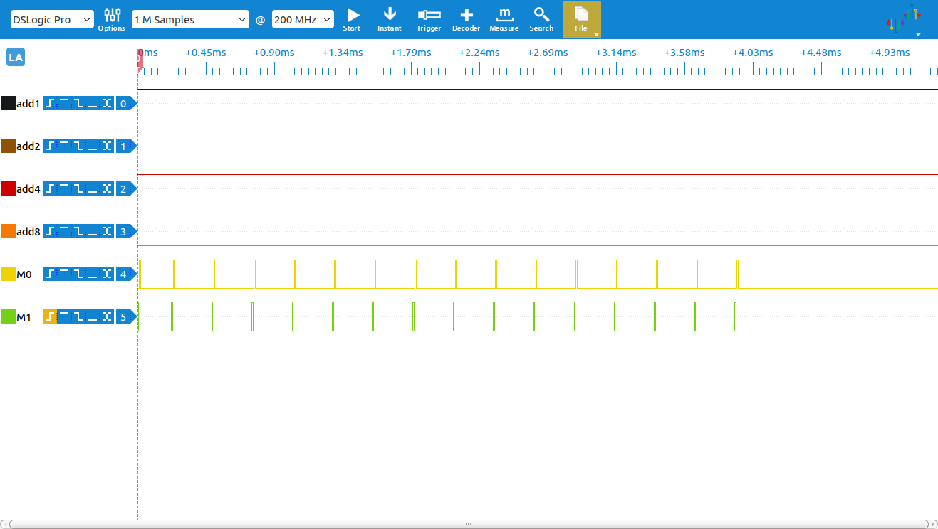
Once the TMS6100 is in a known state the microcomputer waits for a speech command to be issued either by the user or by a running program.
The BBC Micro provides two primary methods of selecting and playing back a voice sample; the first method is by providing an ‘absolute’ location for the sample which results in the TMS6100 receiving a single address followed by a read data command. The Load Address command execution can be seen in the following logic analyzer trace:
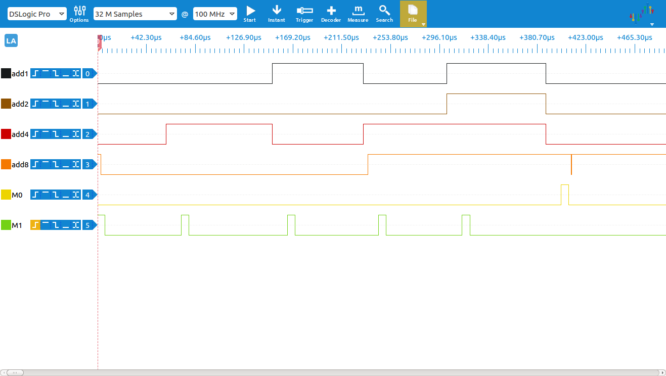
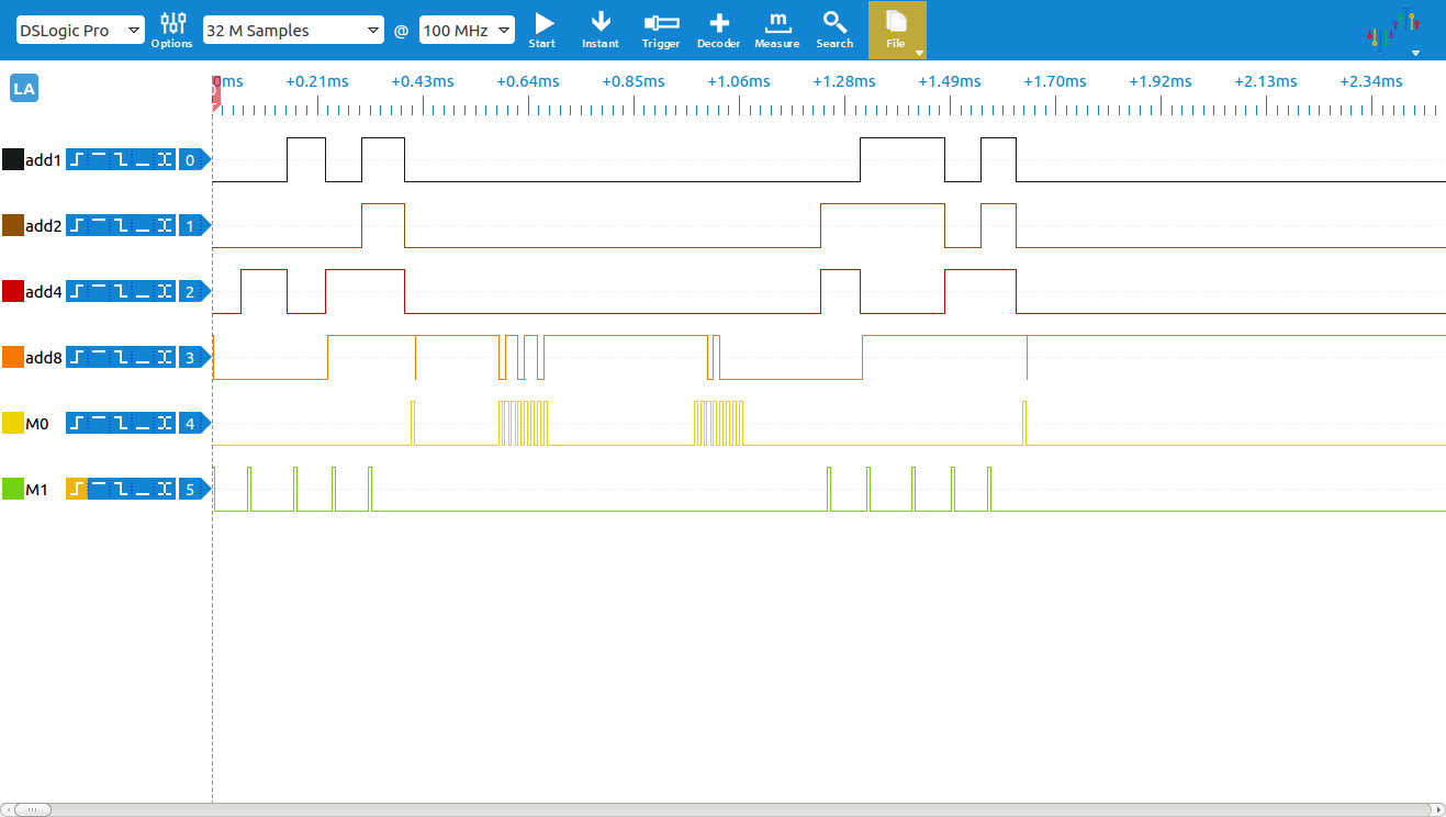
Here you can see M1 go high and the load address command is triggered by the rising edge of M1. The TMS5220 sends 5 nibbles of data 4-bits at a time over the ADD1-8 address bus pins. The address is sent from the least significant nibble to the most significant. The 2 most significant bits are ignored by the TMS6100 and the 4 remaining MSBs are the chip select bits. The remaining 14 bits are the address the TMS6100. Since the Acorn PHROM also contains look-up tables to the sample pointers, it is also possible to provide a ‘word number’ that causes the microcontroller to issue a load address (into the pointer table), a read data (to search for the require absolute address), another load address (to point to the sample) and, finally, another read data to read the actual sample data. An example of this can be seen in the following trace (caused by a SOUND -1, 160,0,0 command):
Once a valid address is loaded, data transfer is started by a single pulse of M0 (as can be seen in the previous two traces). This signals the TMS6100 to go into transfer mode. In the emulation this is used to turn on the SPI peripheral and hand control of ADD8 and M0 over to SPI. If the emulator detects a pulse on M1 control is handed back and the SPI is turned off ready for load address and dummy read commands again.
The SPI format used by the TMS6100 is a little unusual in that the clock phase is not in sync with either the rising or falling edge of the SPI clock (and in that the M1 phase is leading edge and the M0 phase is trailing edge). This can be seen in the following timing diagram from the TMS6100 data sheet:
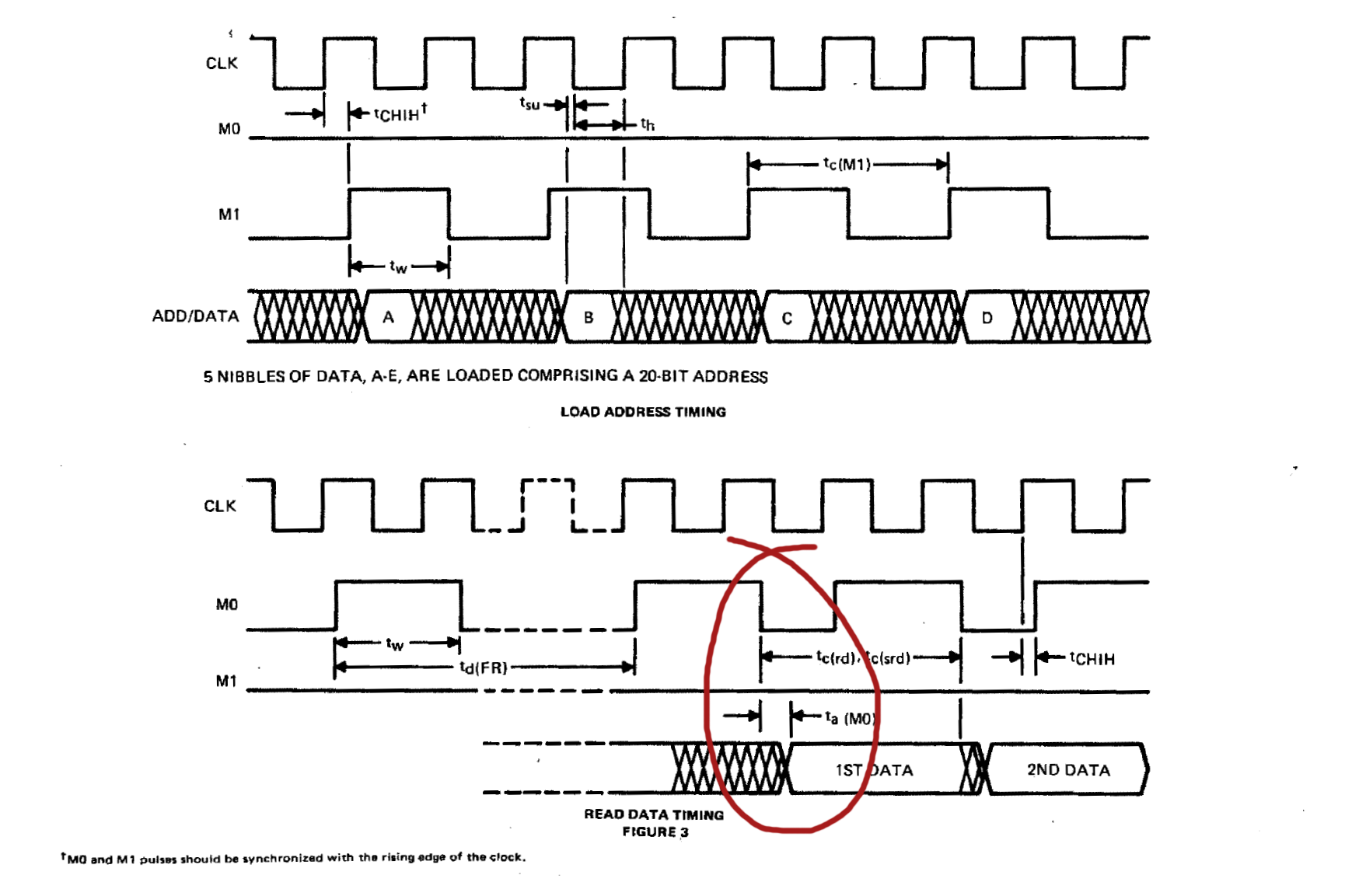
This is not possible to emulate using the SPI peripheral of the ATmega32U2 so, instead, the data is sampled on the rising edge of M0. Since this delay is very short it has no effect on the read data command and functions as shown in the following trace of the emulator performing a read data command (mid-data transfer of 8 bits):
The trace above also shows the approximate transfer rate of the SPI clock which is around 75KHz.
For complete details of the firmware please see the numerous comments in the source code that attempt to explain all of the emulation functions.
Use in other microcomputers
The function of the TMS6100 is common across all types of microcomputers that use the TMS5220 chipset and the PHROM data can be easily modified to represent data other than the Acorn PHROM. If you would like to use the emulator in machines other than the BBC Micro, care should be taken to ensure that the CS pin of the TMS6100 is tied directly to ground as the emulator relies on this for 5V power (the original chip used 5V and -5V). Only the features required by the Acorn implementation are included in the firmware; the comments in the firmware source-code state both the supported and unsupported features, so please examine the code for detailed explanation of the implementation.
By default the firmware will compile to include the Acorn Speech System PHROM data however, if you define the pre-processor symbol PHROM_US, the firmware will compile using the TI American PHROM data (see the source code for details).
Conclusions
Building this emulator was an interesting exercise in reverse-engineering (especially since I don’t have an original TMS6100 PHROM) and allows BBC Micro enthusiasts to provide a low-cost upgrade to their computers. The design is deliberately simplistic in that I tried to keep the component cost and PCB complexity to a minimum to make it as easy and cheap as possible to build. Since this is an open source project you are, of course, welcome to make your own, or even make them for others.
Files for download
The Atmel Studio 7 firmware project files for the project and the KiCAD files for the project (schematic and PCB design) are available on Github:
Hi Simon,
I am interested in developing this as a commercially viable product, ie getting the pcb professionally fabricated with the components assembled as a complete package. I understand the working of the circuit but am unsure on the ATMEGA side. I am assuming that the chip needs flashing/programming with the correct PHROM to write the neccessary data to the ATMEGA, I am more used to programming 16K eeproms.
I would like to ask your permission in the first instance if you would be happy with me getting this made? And also point me in the right direction for the programming side, I have got the atmel studio package but am unsure as to what else I would need to program the chip (I have a TL866) Any help would be gratefully appreciated, it is a great project and as there is very little available (proper TMS6100) virtually impossible. I think it is a viable way to go.
Regards
Martin
Since the project is open-source, open-hardware you are quite welcome to make it and sell it. I’d appreciate it if you would attribute the project by linking to this page. To program the AVR you need an Atmel ISP programmer (the same type as used to program the Arduino style boards).
The programming pins are exposed by the board design (MOSI, MISO, SCLK and RESET); programming is performed by putting the finished board into a breadboard and connecting the programmer to the correct pins. You will also need to power the board during programming (i.e. connect the 5V and ground pins).
Just drop me a note if anything is unclear.
Thanks for the reply, I don’t have a website but I will add a link to this project via the 8bs site and any other forums that I am currently a member of, the more people that know about this the better! I take it that something like the AVRISP MkII would be suitable for the programming as it has it’s own 5v supply powered from USB so it would be only a matter of connecting to the pinouts and then programming via atmel studio?
I will keep you updated of how I am getting on, once I am in possession of the PCB’s then I may need a bit of help with the programming if that is OK by you.
Regards
Martin
I was just wondering if this could be adapted for the Texas Instruments TI-99/4A computer? It has a voice synth addon that uses the 5220 and two 6100s. There’s an internal voice synth mod, and I’d like to do that without sacrificing a working voice synth addon on my ’99. ROM dumps do exist of this cart, I’ve heard.
The project is open-source so you should be able to adapt it to any PHROM image you like. I don’t have a TI-99/4A though, so I have no way to verify compatibility.
Alright, I will have to rack my brains on how to adapt the online ROM dumps of the stacked ROMs into a useable image for the TMS6100 emulator. I’m still a noob and learning as I go, heh.