RGB LED Love Heart
Contents
This project creates a RGB LED lit love heart which is controlled by a PIC12F683 microcontroller. I designed the project as a gift for my wife on our 15th wedding anniversary (since she puts up with my addiction to electronics I thought she deserved something in return!).
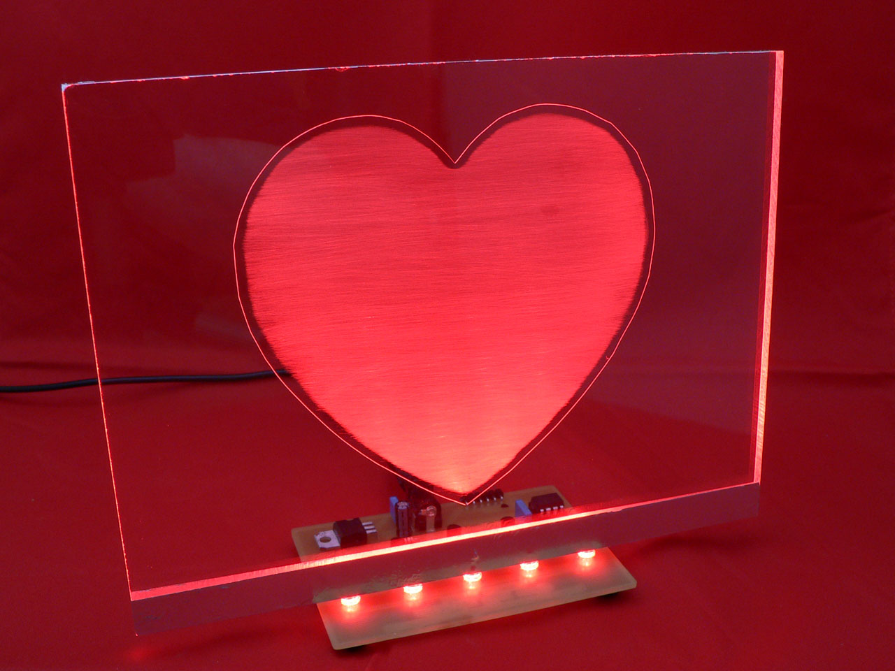
The love heart is made from a 200x150x6mm sheet of plexi-glass which is cut and sanded to create the optical effect and then mounted on the control board. Even if you are not into microcontrollers the display can be easily adapted to show any shape (or shapes) you like; furthermore any high-intensity LEDs can be used allowing you to create a static light display using little more than some LEDs, resistors and a power source.
YouTube Demonstration Video
Note: The high brightness LEDs, PWM colour mixing and the varying intensities confuse my video camera a lot and it seems that the camera is overly sensitive to blue. Despite this I hope the video gives you some idea of how the display functions; the display outputs 35 unique colours fading between each.
Parts list
To build this project you will need some basic tools in order to work with the plexiglass. In addition you will need a PCB (printed circuit board) which you can either make yourself, or use my supplied Eagle CAD files to order a PCB from one of the many board producers available on the Internet.
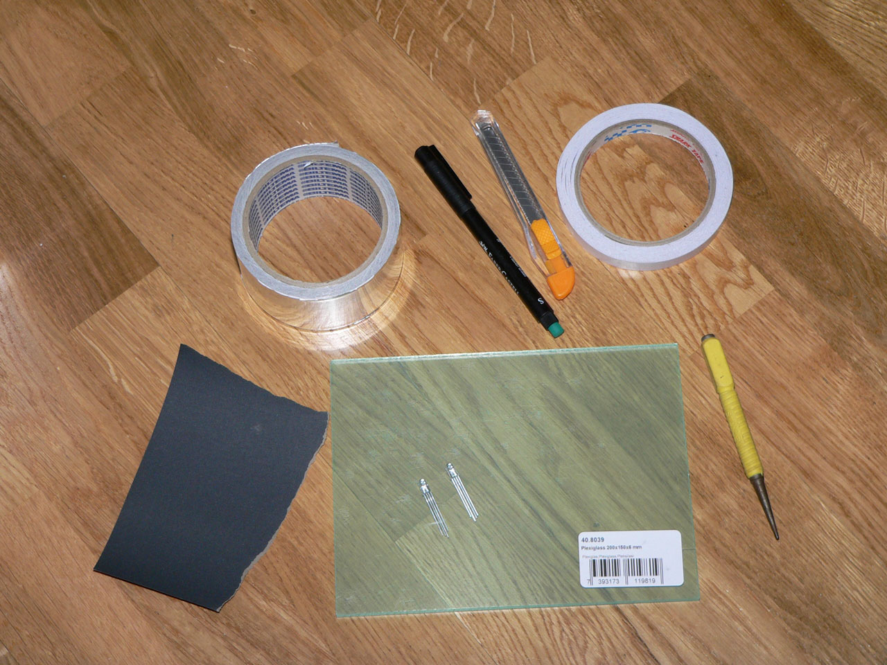
You will need:
- 1x 200x150x6mm sheet of plexi-glass
- 1x Aluminium tape
- 1x Double-sided sticky tape
- 1x P600 and/or P1200 fine grain sand-paper
- 1x sharp hobby knife
- 1x dot-punch
- 1x black fine-line marker pen
- 1x Printed Circuit Board
- 1x PIC12F683
- 1x DIP-8 IC Socket
- 3x 1K Ohm resistor
- 10x 56R resistor
- 5x 120R resistor
- 5x High-intensity RGB LEDs (common anode)
- 2x 100nF capacitors
- 1x 10uF capacitor
- 1x 7805 5V Regulator
- 1x 2.1mm DC Jack
- 3x BC337 NPN Transistors
- 1x 6 pin right-angle 2.54mm header (optional)
If you don’t want to build the more complex RGB LED controller you can use 5 high intensity red LEDs and resistors instead.
The Controller Board
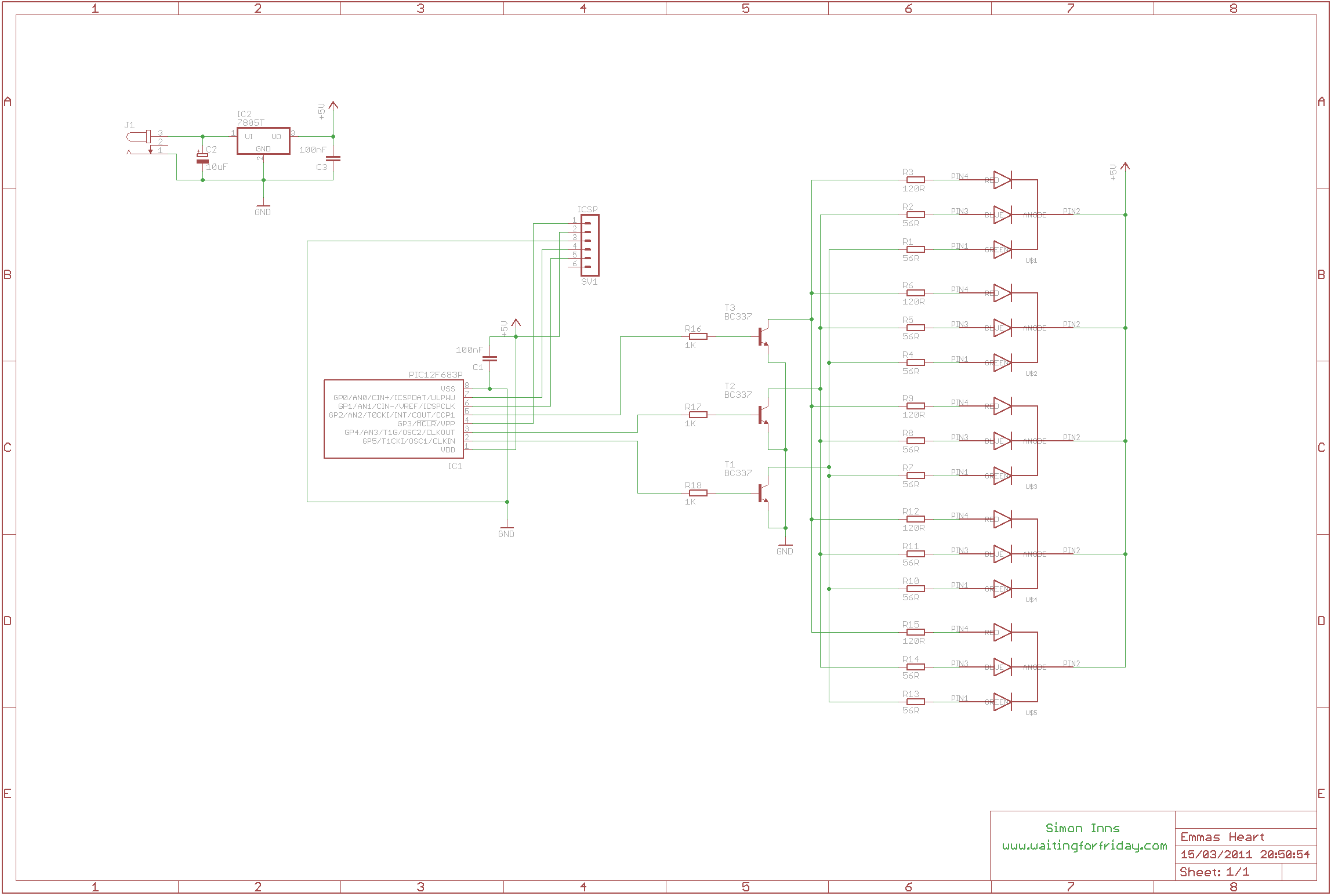
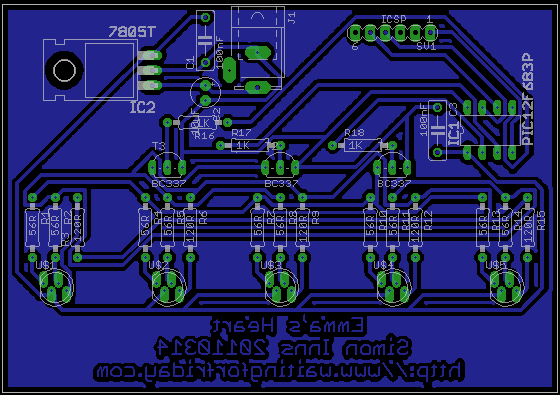
The controller board circuit diagram and PCB artwork are shown below. The Eagle CAD files for these items are included with the project files so you can adapt and alter the design to your needs (as is the firmware for the PIC12F683 written in HiTech PIC C).
The board works by generating 3 software PWM signals from the PIC which control the overall brightness of the red, green and blue LEDs. Since the LEDs require 30mA per led colour the circuit must be capable of sinking 90mA per colour or 5x90mA = 450mA which is way over the rated maximum of the PIC. Therefore BC337 small signal transistors (which can handle 800mA each) are used to sink the current coming from the LEDs. The PIC controls the BC337 via 1K resistors which limit the current output from the PIC.
The sinking current to each LED colour is limited to 30mA by 3 transistors (one for each colour). Since the RGB LEDs I used have different ratings for the red channel (lower forward current) the red channel requires a different resistance value from the green and blue channels.
5 volts of power (at 1A max) is supplied by the 7805 voltage regulator. If you use a power supply of 9 Volts, you shouldn’t need a heatsink on the 7805 as it will run only at around 50-60C.
The PCB should be assembled starting with the smallest components (the resistors) and working up to the largest (the 2.1mm DC Jack). As a final step you should insert the PIC12F683 into its DIP-8 socket. If you want to program the PIC in-circuit (through the optional ICSP header) you will need to connect pins 2 and 3 from the header to Vcc and Vdd using some fine gauge wire in order for the ICSP programmer to function (I did not include this on the PCB as it would require 2 jumper wires which would degrade the clean look of the single-sided PCB design). These wires can easily be added to the copper-side of the PCB.
The RGB LEDs I used are capable of being driven at 30mA and produce a lot of light. You will need to check the datasheet for your LEDs and, if necessary, adjust the resistor values to make sure you do not supply too much current to your lights. If in doubt use 150R resistors (which is usually a safe maximum for most LEDs).
The PIC12F683 Firmware
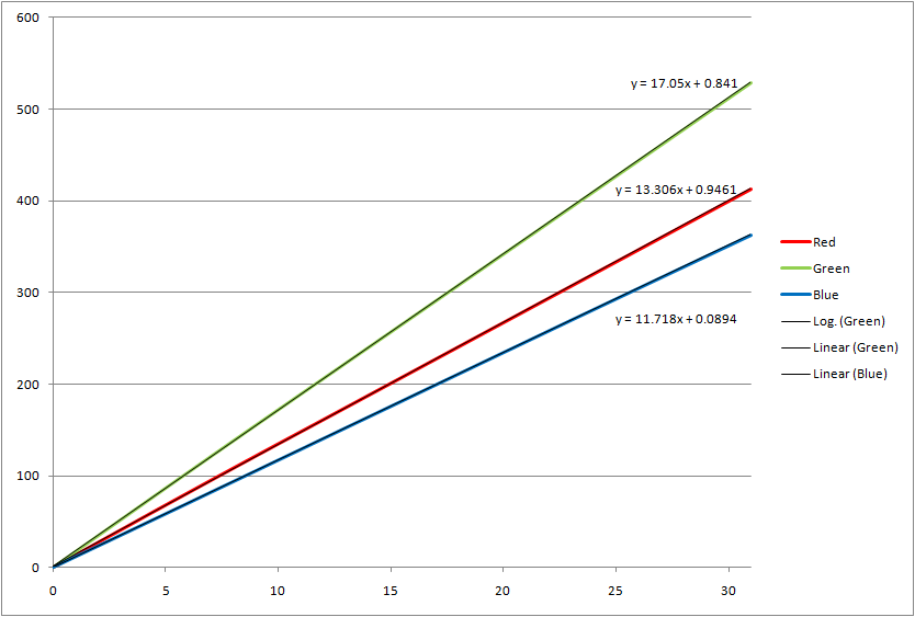
The firmware is written in HiTech PICC and is included with the project files. The firmware consists of an interrupt driven software PWM driver which controls the RGB LEDs at 100Hz and supports 32 brightness levels per colour. RGB LEDs do not have a uniform output brightness across the 3 available colours; this means that you have to be careful to calculate the white balance (ensuring the each colour produces the same brightness when mixing colours).
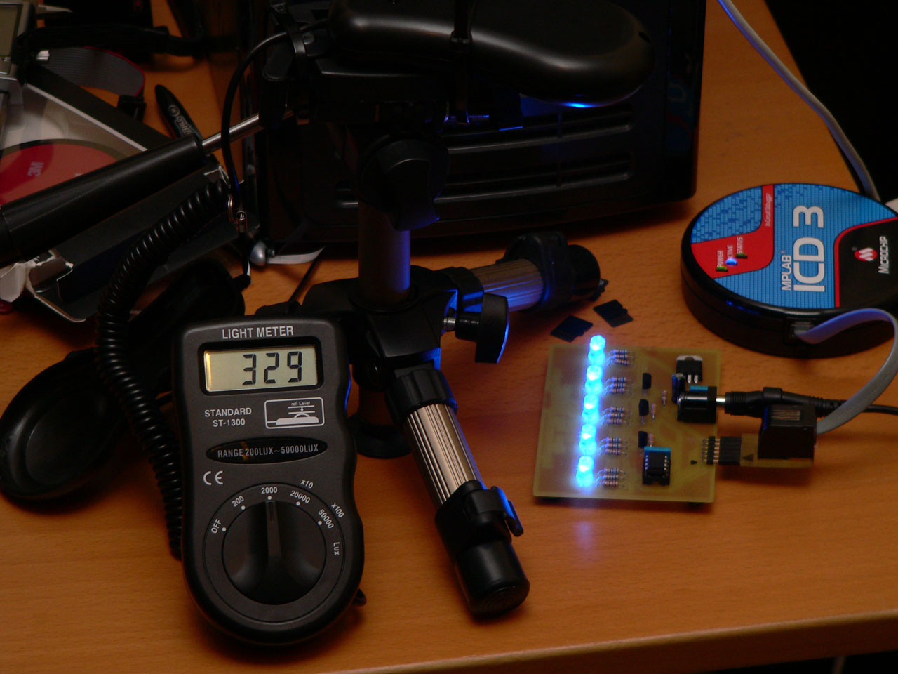
To do this I used a standard LUX meter to measure the brightness of the individual LEDs and then entered the resulting information into a table in the firmware to ensure that the colour mixing was as even as possible. The graph above shows the intensities of the colours within a LED across the 32 available brightness levels. The white-balance table was created from the trend-line equations which are automatically generated by Microsoft Excel. The second picture shows the set-up of the LUX meter used to create the graph. All three colours we measured from a constant distance with LUX shown on the vertical axis and the brightness level (0-31) on the horizontal axis).
The white-balance varies from LED to LED so you may need to consult your LED’s data sheet, or simply experiment with the table’s values to make sure the resulting colours are correct for your RGB LEDs.
Preparing the Plexi-glass
Cutting and drilling plexi-glass is a little tricky as the material is prone to melting and shattering. As well as ensuring you use a relatively slow drill speed you should also ensure that you wear the correct protective equipment at all times. In particular safety goggles are a must when working.
Drilling the 5 holes for the LEDs requires precision since the hole needs to be 5mm in diameter and the overall thickness of the material is 6mms giving a 0.5mm tolerance for mistakes (!)… Drilling with this much accuracy requires a 5 stage approach:
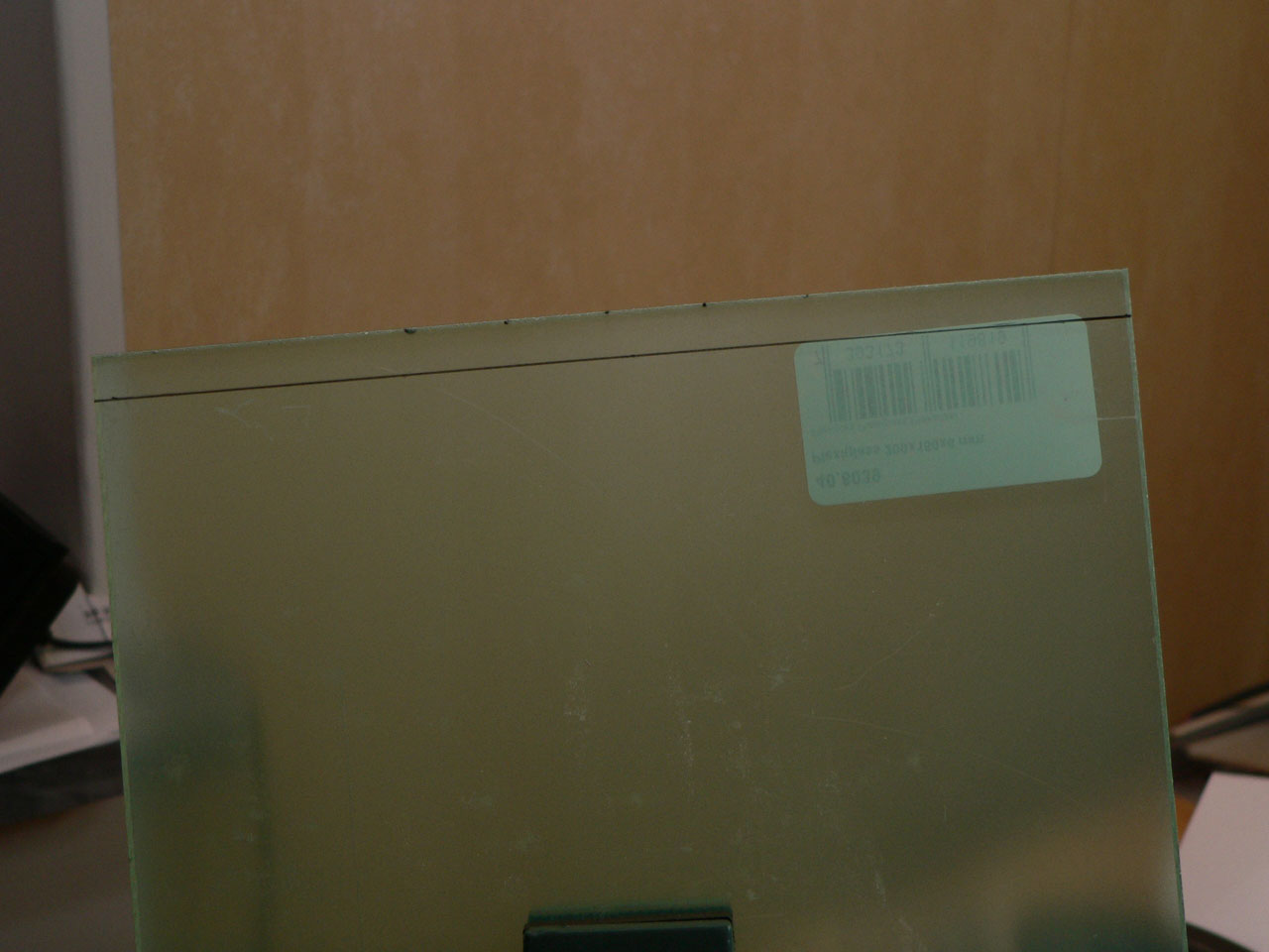
1) Firstly mark accurately the centre points of the LEDs from the PCB; although you can take these measurements from the design it is better to have made the PCB first and then (from the centre of the plexi-glass) mark off the centre positions of the 5 LEDs. Once this is done measure and mark exactly 3mm from the edge of the plexiglass to create a cross for each hole (see the picture for details).
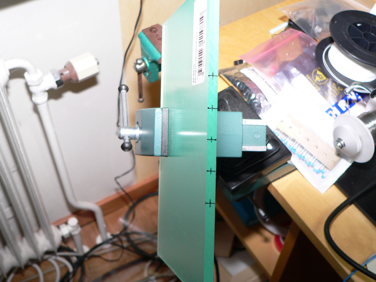
2) Draw a line across the plexi-glass to show how deep you require the holes to be. This will be 8-10mm depending on the design of the LEDs you are using.
3) Next use the dot-punch and (lightly!) punch a small indentation in the middle of every cross. This will help guide the drill-bit into the correct spot and prevent it from slipping and giving you an off-centre hole. You should be very careful to make the dot as central to your marking as possible.
4) Now take a drill-bit less then 2mm in diameter and (using the dot-punch marks) drill a hole down in to the plexi-glass which will be used to guide the main drill-bit in the next step.
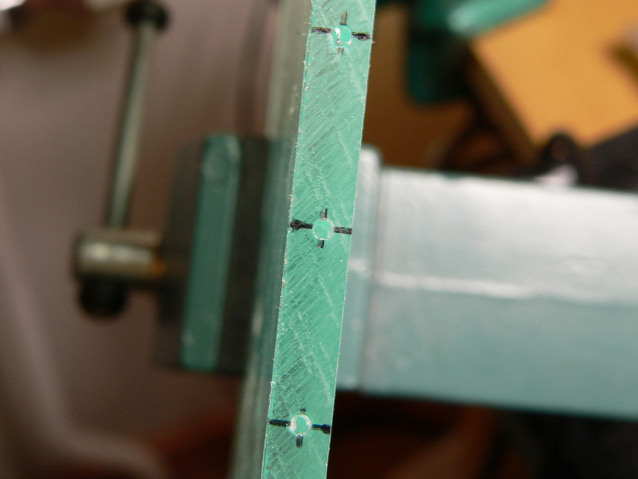
5) As a final step use a 5mm drill-bit to drill out the holes to allow the LEDs to be mounted inside the plexi-glass. Once the holes are drilled you should carefully remove any excess plastic in the holes.
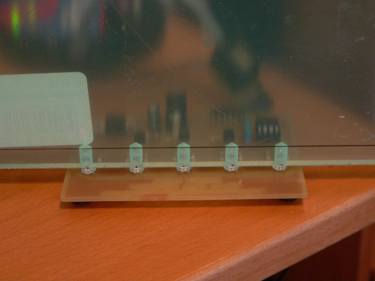
Once completed the plexi-glass should fit snugly over the 5 LEDs on the controller board.
Note: Whatever you do, do not be tempted to peal off the plexi-glass’ protective plastic until you are completely finished handling the material… If you do it will get scratched and there is nothing you can do about it! 🙂
Creating the love heart design
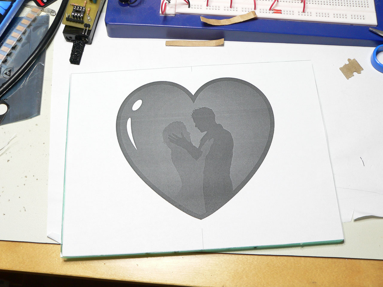
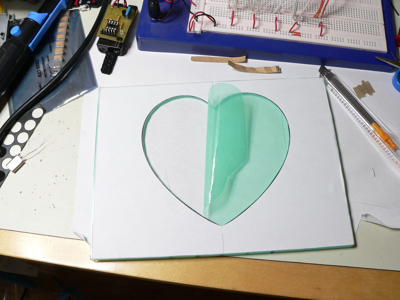
To create the love heart design print out and cut out the template included in the project files. Apply strips of double-sided tape across the plexiglass (make sure to use as much tape as possible so the template is held in position when you cut it later).
Apply the template to the plexi-glass ensuring that it is as smooth as possible. Next take your hobby knife and cut around the outside of the template. Make sure that you do not remove the knife from the surface whilst cutting. Keep the knife pressed and rotate the plexi-glass as you go. This will ensure that the heart’s outline is a single line without any ‘cross-hatching’. Since all cuts and scratches in the plexi-glass will show once lit, this is important.
Once you have cut around the whole shape remove the paper. Be careful not to scratch the surface as you go. Once you have removed the paper use your knife to carefully lift the plastic protection from the plexi-glass within the heart shape (see the picture for an example). You should now be left with an exposed heart-shaped area.
Using some P600 or P1200 sand paper carefully sand the exposed area from left to right and back again (don’t do this in random directions or the end-result will not look so good). You should ensure that you sand the whole area as evenly as possible (make sure to wipe away the excess dust to ensure that you have sanded the area evenly). The combination of the paper template and the protective coating of the plexi-glass will ensure you only sand the correct area.
Once you have finished sanding remove the paper template and the protective plastic coating from the plexi-glass. Now cut some strips of aluminium tape and cover the edges of the plexi-glass and the area in which the LEDs are to be inserted (look at the picture above for details). The aluminium tape will bounce the light inside of the plexi-glass and make sure that the display is as bright as possible.
Using your hobby-knife make sure that you free up the holes for the LEDs as much as possible to ensure that the LEDs fit without problems.
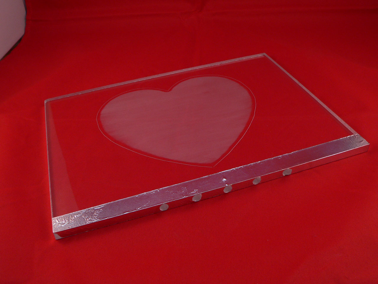
Finally insert the LEDs on the control board into the plexi-glass. The LEDs should fit snugly and should not require glue to hold the display in place. If required use a hot-glue gun to ensure that nothing can move.
You are now ready for action!
Files for download
Attached you will find the project files including the heart template (in PDF format) the HiTech C firmware and the Eagle CAD schematic and PCB files.
I hope you have fun building your own RGB LED plexiglass design and, if you decided to build a love heart, that your wife/girlfriend appreciates it as much as mine did 🙂 !
A PDF of the heart shape used to create this project:
The PCB artwork and schematics in Eagle CAD format:
The PIC12F683 firmware source code (for HiTech C: