Vetinari’s Clock
Contents
In the excellent Discworld series the character Lord Vetinari has a clock in his waiting room which is designed to tick irregularly in order to make his visitor feel ill at ease. Inspired by a post featured on Hackaday I decided to build my own version of this clock with a simple and easy to make design.

Akafugu.jp have released a kit version of this clock based on the ATtiny25 complete with open-source and open-hardware documentation, so if you want to get your very own clock you can purchase one over on their website (note that waitingforfriday.com is not affiliated with Akafugu.jp, so for support and questions on their kit please contact them directly):
YouTube Demonstration Video
Clock controller design
The clock controller simply replaces the built in controller in a standard quartz clock movement. The clock works using a simple stepping motor design which is pulsed every second. With each pulse the polarity is reversed in order to flip-flop the magnetic field of the motor’s electromagnet. The following scope trace shows the output from the original controller:
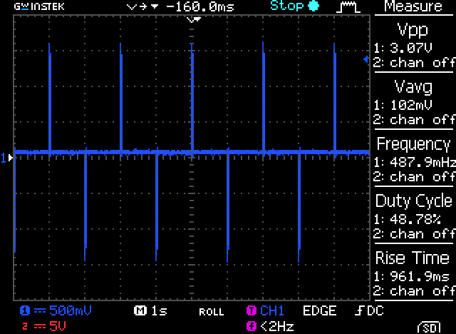
Controller design
The following diagram shows the circuit schematic for the clock controller:
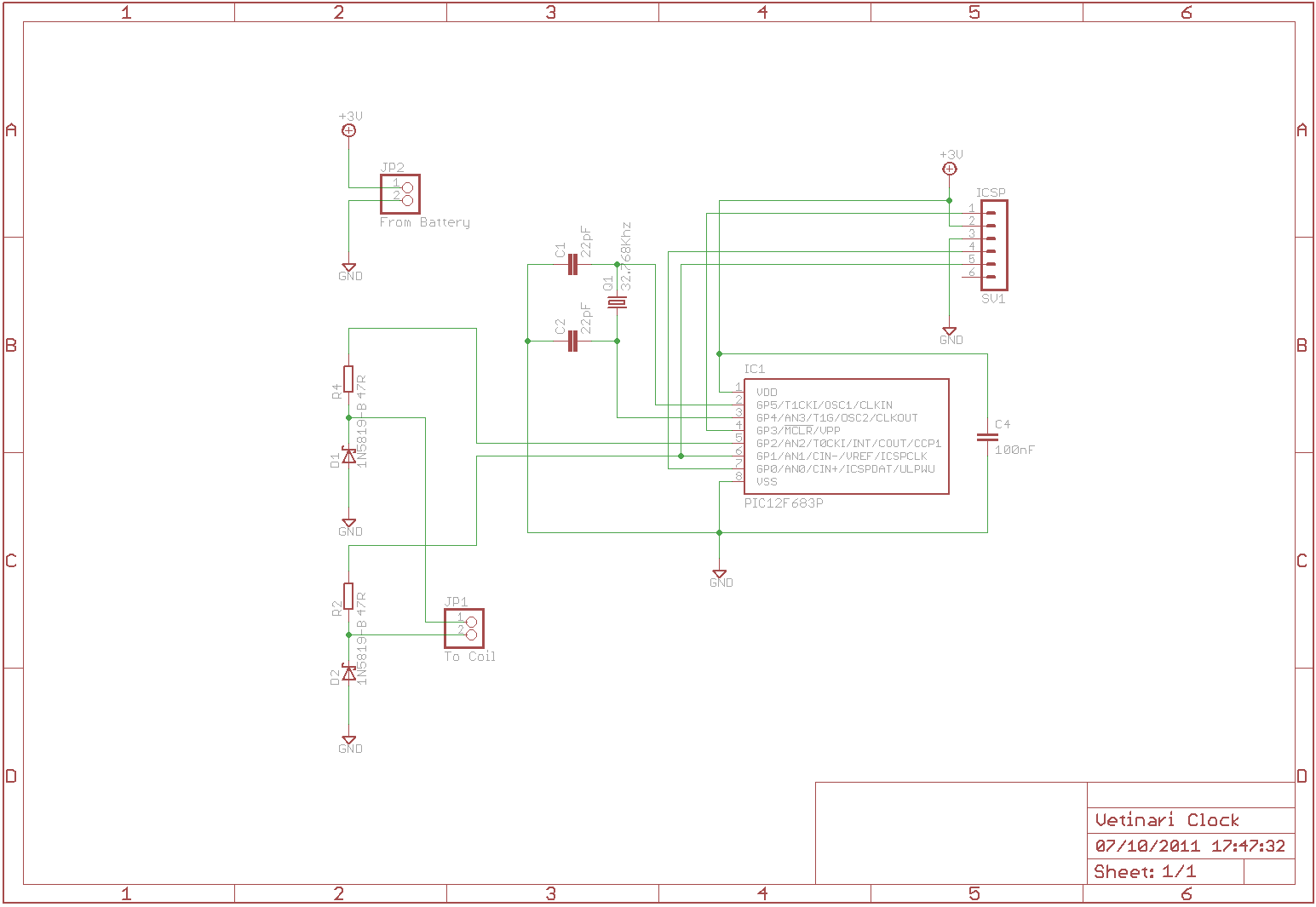
The clock controller uses a PIC12F683 which is externally clocked using a 32.768Khz clock crystal (using the LP oscillator mode). This means that the PIC is running at 32768 clock cycles per second which makes timing the clock very easy to do (and also means you do not need an additional RTC chip). To ensure good time-keeping the firmware uses the overflow of timer0 to cause an interrupt 4 times a second. Since the 8-bit timer starts counting from zero after the overflow the firmware does not loose clock cycles in resetting the timer. This means the clock is as accurate as the crystal and that the PIC consumes very little power since it is running at such a low clock speed.
The firmware has a ‘random’ sequence of pulses which over 32 seconds moves the second hand 32 times. This sequence is long enough to give the appearance of randomness without unnecessarily consuming processor cycles. I chose 32 seconds as it means the pattern is constantly offset from the 60 second rotation of the minutes. The ‘random’ pattern is 128 steps (and is therefore checked 4 times a second). This means the clock moves between 0-4 times within each actual second. By moving more or less in each of the 32 seconds the clock looks random, however the sequence always moves the clock exactly 32 seconds in the 128 steps.
There is also a secondary delay which prevents the clock from advancing the second hand on exactly the quarter second. This adds a little more delay to each movement to provide a more random feeling to the clock.
The clock is pulsed via two current limiting resistors which limit the current draw from the PIC and to the clock. Since the PIC cannot operate on 1.5Vs there are 2AA cells providing 3Vs. The resistors ensure that the clock module runs within its original specification. The two Schottky barrier diodes act as clamps ensuring that the spikes generated by the coil do not exceed the working limits of the PIC processor.
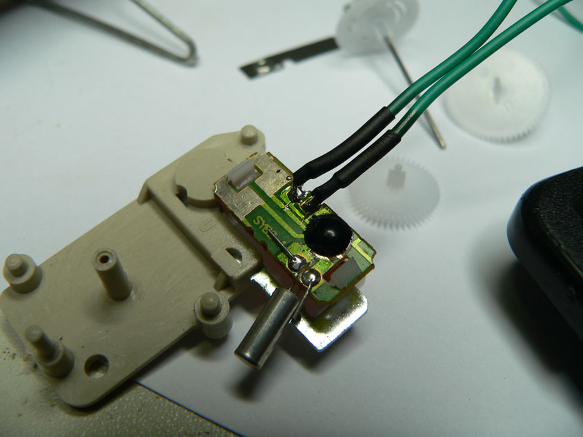
In the following picture you can see the addition wires connected to the clock movement’s coil. I tested with 2 different clocks and did not need to disconnect the coil from the original circuitry for it to function correctly. After soldering the wires are shrink-wrapped to prevent shorts and then a blob of hot glue was placed over the connections to prevent them from being pulled off.
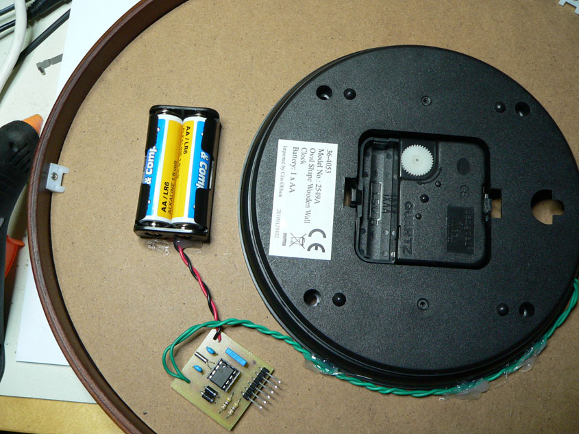
Once connected the quartz movement is connected to the PIC12F control board which (along with the batteries) is simply hot-glued to the back of the clock. The PCB is a very simple single-sided board which requires no jumper wires:
This project can be easily modified for other custom clock control projects and can even be reprogrammed in circuit using the ICSP header on the controller board.
Files for download
Below you will find the project files including the HiTech C firmware and the Eagle CAD schematic and PCB files:
The PCB artwork and schematics in Eagle CAD format:
The PIC12F683 firmware source code (for HiTech C):