RC Servo Processor
Contents
On a continuing mission to build an autonomous sailing robot we needed a way to more rapidly prototype boat designs and wanted to use a standard remote control model control system to save time by using off-the-shelf parts. When controlling servos with microcontroller based electronics you can use the full 180 degrees of rotation; however standard RC systems typically only support 90 degrees or less. We also needed a way to limit the rotational speed of the servos to prevent wear and damage to parts of the boat.
The RC Servo Processor is a simple and small device which sits in between your RC receiver and servo which allows you to control both the rotation range and speed of a servo. Using only 4 components it is small, light and power efficient.
YouTube Demonstration Video
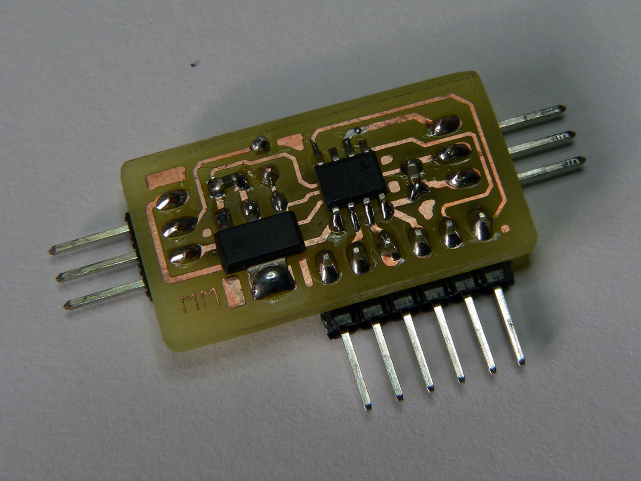
The RC Servo Processor Board
The RC Servo Processor allows you to define the expected range of input from your RC controller and then map that range on to your desired output. This is performed by simply changing some #define statements in the PIC12F source code. The firmware takes care of calculating the required PWM output to the servo by scaling the available input range to the desired output.
To set up the firmware you must first specify the range of output your RC controller supports, this is typically around 1100uS to 1900uS:
// Definitions for RC Receiver input (in units of 0.5uS)
// 1146uS to 1889 uS
#define RX_MIN_WIDTH	1146*2
#define RX_MAX_WIDTH	1889*2
The you can specify the desired output range using the following define statements:
// Definitions for RC Servo output (in units of 0.5uS)
// 400uS to 2150uS
#define SERVO_MIN_WIDTH	400*2
#define SERVO_MAX_WIDTH	2150*2
Note that the units are in 0.5uS, so 400uS is 800 (which is why the definitions contain the *2 to make it clearer). Finally there are 2 more supported settings; the rotational speed limit – this can be set to 0 for no limit, or it represents the maximum difference in uS from pulse-to-pulse generated by the RC receiver (so this is typically the maximum change in 1/50th of a second). You can also set up the number of samples which are used to measure the RC controllers output. Since the PIC12F is using the internal oscillator, averaging the readings helps to prevent jitter in the output:
// Rotational Speed limitation for output servo
// Set to zero for no limit or specify the maximum allowed pulse width variation
// per output pulse (in units of 0.5uS).  Note: the actual speed of the output
// pulses is dependent on the RC Receiver output, but is typically one pulse per
// 20mS (50 pulses per second).
#define SERVO_SPEED_LIMIT 0
// Number of samples to average the positive pulse width from (2-5)
#define NO_OF_SAMPLES 4
The firmware takes advantage of the fact that RC control systems send a control pulse of around 1-2mS followed by a pause of 20-30mS. The PIC12F samples the pulse from the RC receiver and then performs all the required calculations for the output pulse during the relatively long gap before sending the pulse to the target. This means that the firmware can be coded without the need for interrupts and helps to keep the timing stable.
Circuit Schematic
The following diagram shows the circuit schematic for the RC Servo Processor:
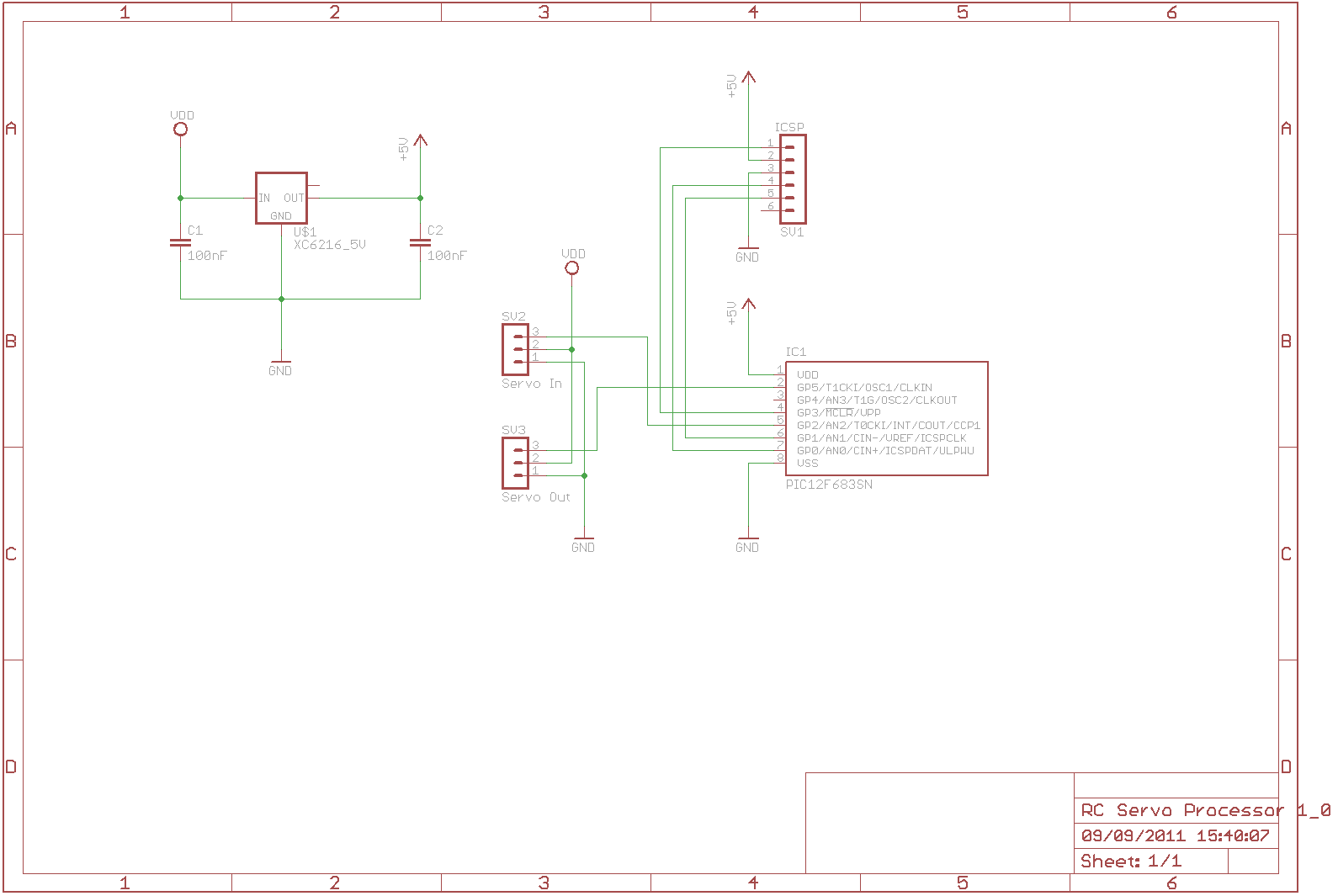
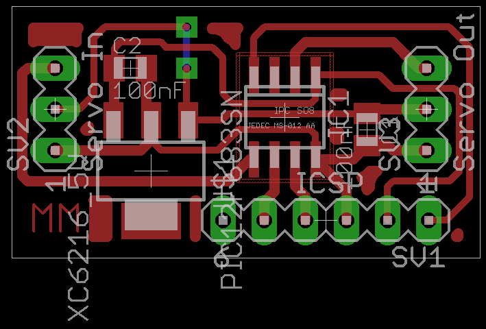
The PCB is designed to be as simple and compact as possible. By placing the 5V Regulator and PIC close together the design requires only 2 100nF capacitors to stabilise the power on either side of the regulator. The board draws its power from the servo power feed, however due to the on-board regulator it can operate with battery packs greater than 5Vs without issue:
Files for download
Below you will find the project files including the HiTech C firmware and the Eagle CAD schematic and PCB files:
The PCB artwork and schematics in Eagle CAD format:
The PIC12F683 firmware source code (for HiTech C):