MicroSimon
Contents
This project shows how to create an MB Electronics Simon game clone using an 8-pin PIC12F683 microcontroller. The game includes a full emulation of the original Simon ‘game 1’ and the ability to select from 4 skill levels which control the number of colours you must repeat in a sequence in order to win the game.
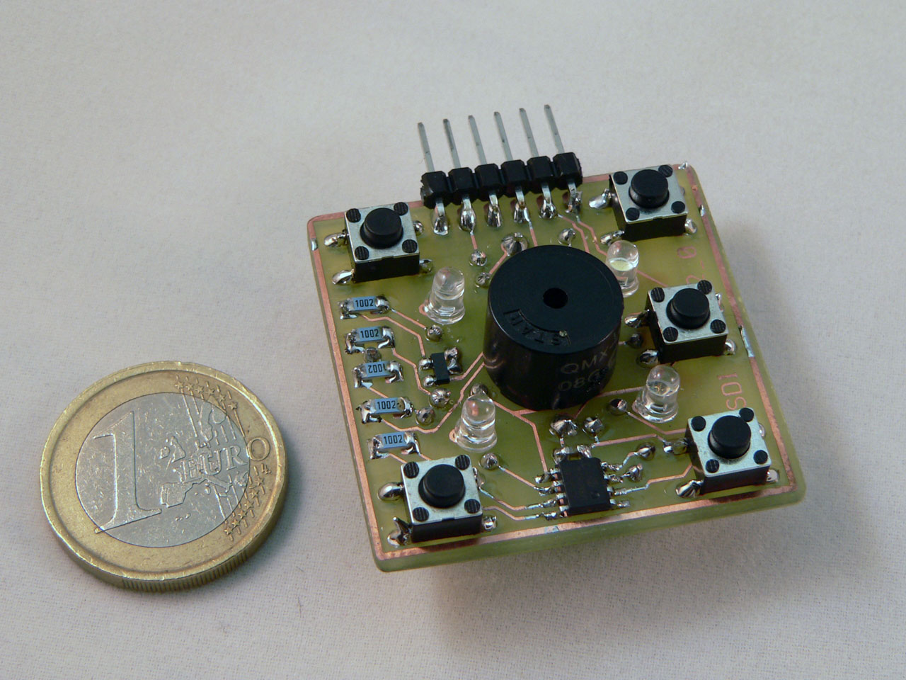
The project was created for Sparkfun’s microcontroller competition 2011 and aims to demonstrate a number of useful design techniques which can be used when working with low-pin count microcontrollers. The code is written entirely in C and fits neatly into the 2K of available program flash on the chip. The PCB is only 1.5 inches square and uses both SMD and through-hole components, however it is perfectly possible to recreate the project using larger components on a breadboard or a small piece of strip-board.
The game is powered by a stanard CR2032 3V lithium cell which is mounted on the underside of the game. The design uses the ultra low power standby feature of the microcontroller meaning that no power switch is required. Overall power consumption is kept to a minimum by using the internal oscillator of the PIC running at 4Mhz.
YouTube Demonstration Video
Hardware
Parts list
The MicroSimon hardware consists of the following parts:
- 1 x PIC12F683 SOIC 8-pin microcontroller
- 5 x 10K resistors (1206 SMD)
- 1 x BC817 NPN Transistor
- 1 x 100nF capacitor (0805 SMD)
- 4 x 3mm LEDs
- 1 x CR2032 battery holder
- 5 x Tactile push-button switches
- 1 x QMX-05 speaker
- 1 x 6 pin 2.54″ right angled header
Circuit Schematic
The Eagle CAD schematics and board files are available for download with the project files. Here is a schematic of the overall hardware:
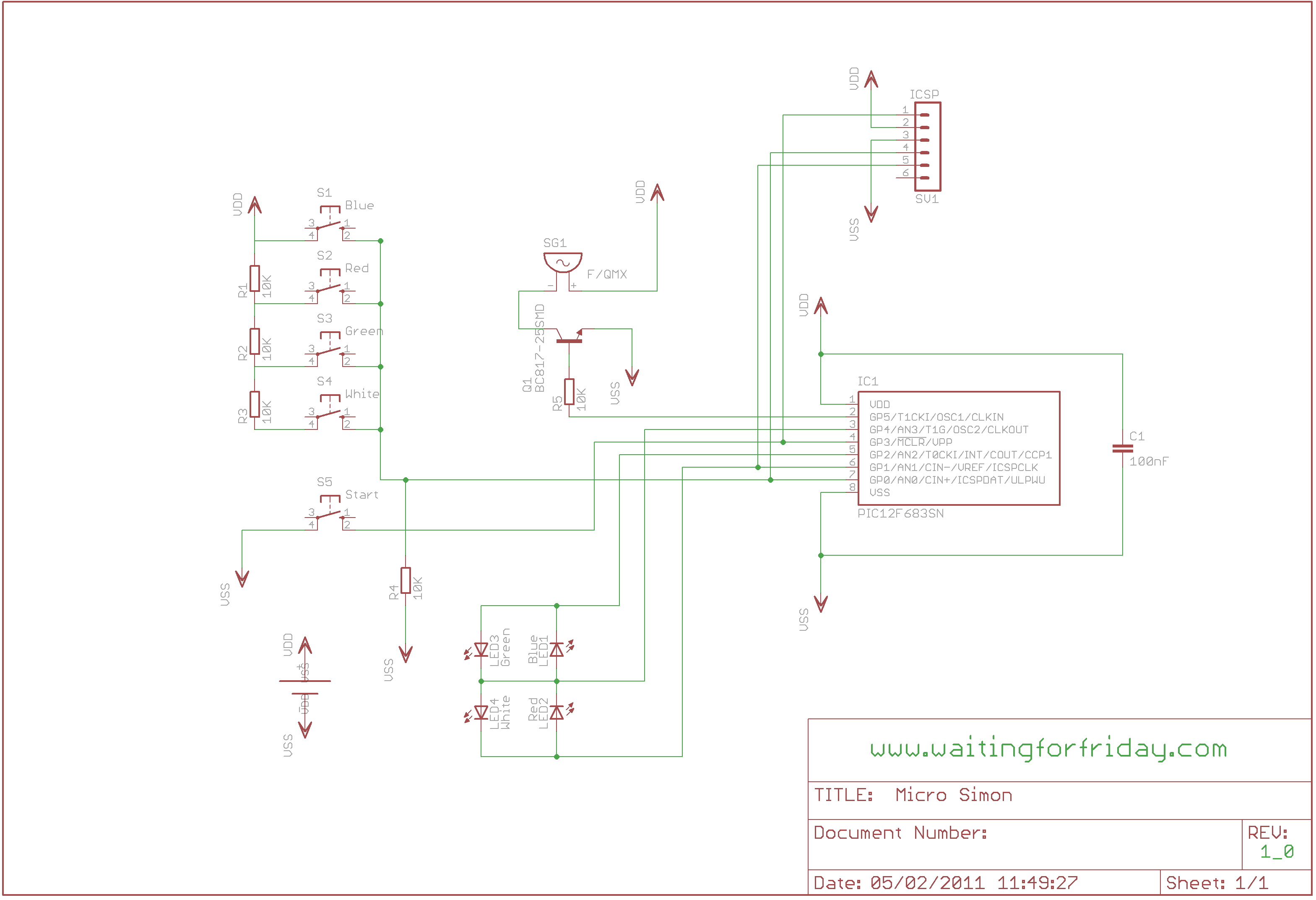
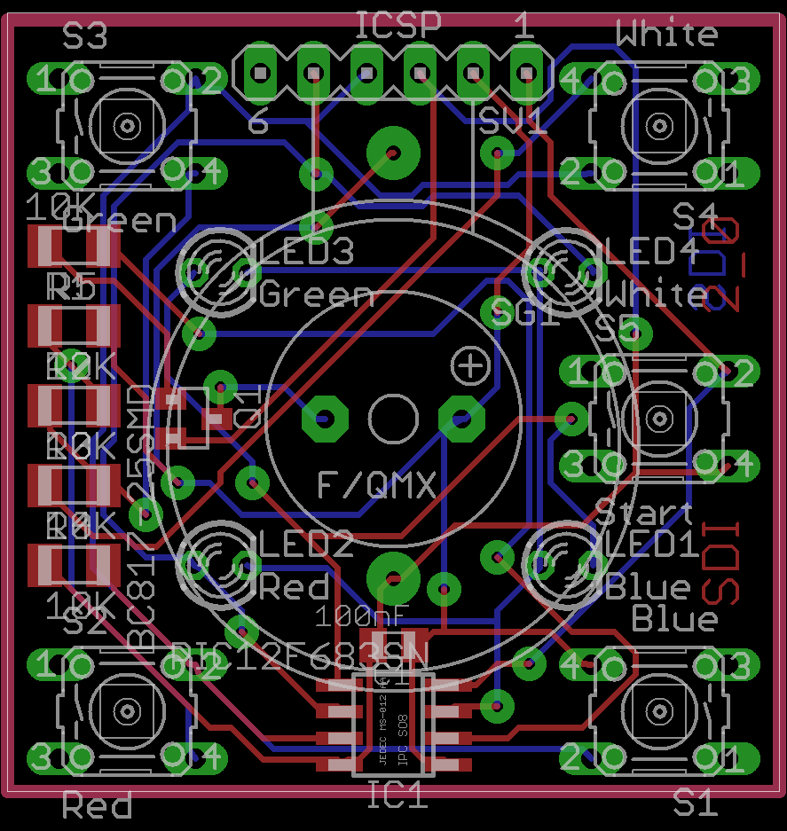
The board is a small dual-layer PCB, all components are mounted top-side apart from the battery holder which is mounted on the bottom of the board to save space. I tried to make the board as small as possible whilst still being playable (I have big thumbs!). The in-circuit programming header can be omitted if not required to make the hardware neater looking. The PCB was made using the UV photo-resist technique which allows for good track accuracy even from a hobbyist set up. Here is a picture of the board created in Eagle:
4 Switches on 1 ADC pin
The hardware design uses a common microcontroller trick of using a single ADC (Analogue to Digital Converter) pin to connect the 4 colour buttons of the game. Each switch is connected to the controller through a single ‘pull-down’ resistor to earth which acts as the lower half of the voltage divider. The other half of the voltage divider is created using a network of 10K resistors on the other side of the push-buttons. Depending on what button you press you connect either 0 Ohms, 10K Ohms, 20K Ohms or 30K Ohms to the top half of the voltage divider. Using some simple ohms-law maths you can then work out the voltage for any given switch as shown in the following diagram:
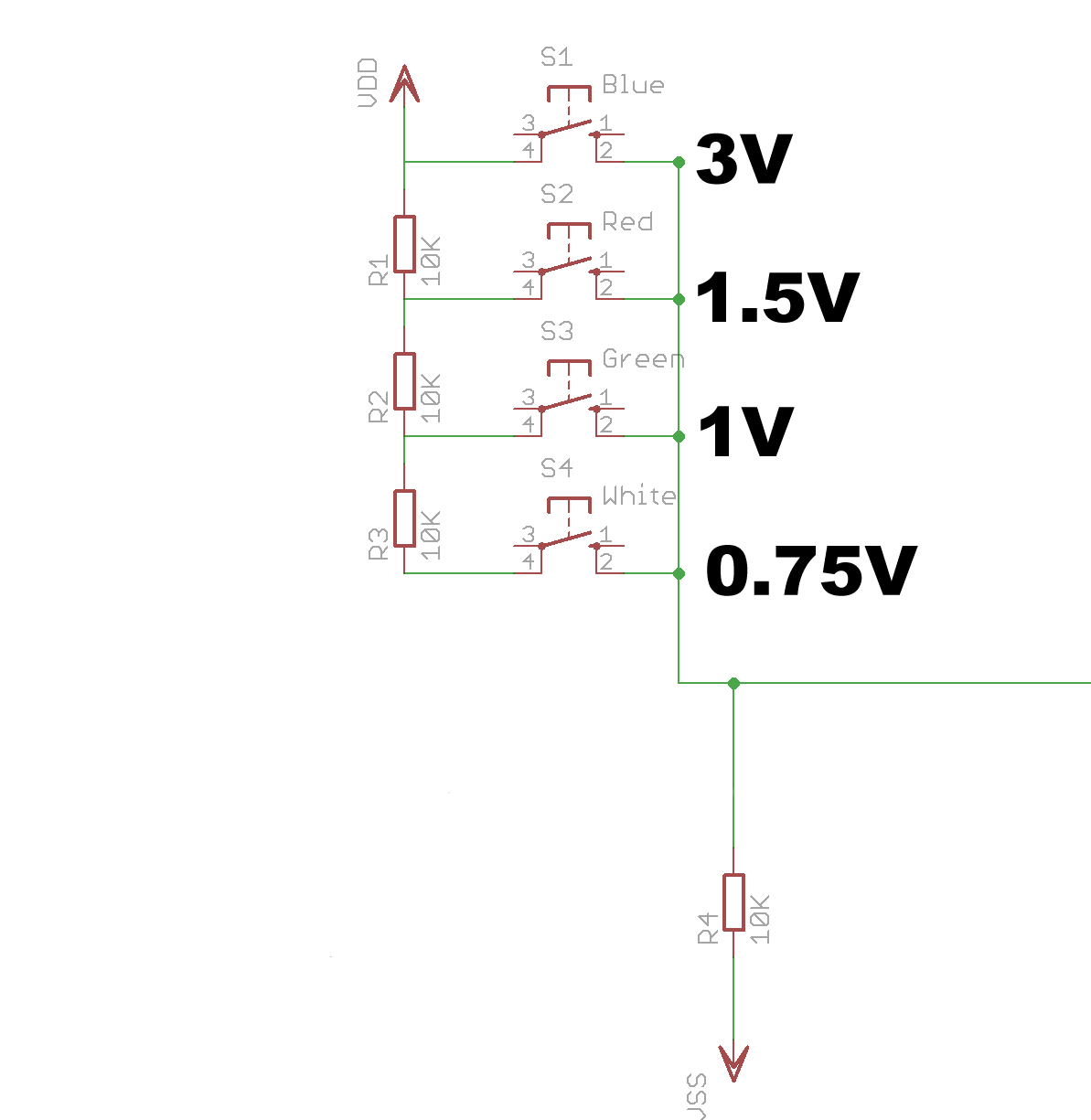
The software simply polls the ADC converter and reads a 10-bit conversion value for the pin (0-1023 with 0 being Vss and 1023 being Vdd). Each button is allocated a small range of possible values to allow for variance in the values of the resistors. The nice thing about this design is that the processor uses Vdd (3 volts) as the reference for the conversion so even as the battery drains it is still accurate since the input voltage to the divider and the PIC’s Vref is the same.
Low-Power Sleep
Instead of using a bulky toggle switch for the power control the hardware uses the low-power sleep mode available on the PIC. The ‘start’ button for the game is actually a MCLR reset button. When the PIC is reset the game starts, once the game is over the PIC enters low-power sleep. Pressing the reset button resets the controller and the game starts again. The power drain of the PIC in sleep mode is very low so it would take some considerable time for it to deplete the 3V battery.
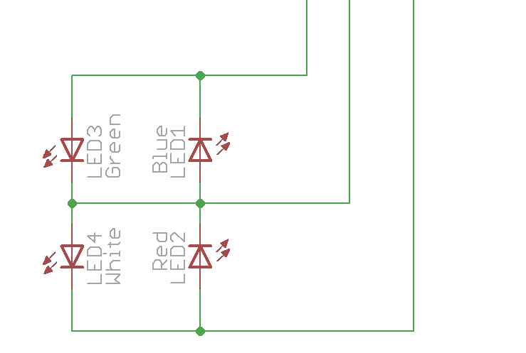
Charlieplexed LEDs
The LEDs are connected to the PIC using 3 pins. This is achieved by using ‘charlieplexing’ which takes advantage of the fact that an LED is a diode and only allows power to flow in one direction. The PIC’s IO pins are ‘tri-state’ meaning they can be 0V (sinking power to ground), 3V (sourcing power from Vdd) or ‘high-impedance’ inputs (high impedance is a fancy expression meaning that the pin is effectively disconnected and virtually no power flows through it). Using 3 pins it is possible to control up to 6 LEDs, however the game only requires 4 as shown in the following diagram:
Sound Generation
The sound circuitry consists of a miniature QMX-05 speaker with a single NPN transistor which makes the sound louder and also avoids placing a high load on the microcontroller’s output pin. It is possible to drive the speaker directly from the PIC without using the resistor or transistor, however this results in a much weaker sound. If you want to build the circuit using larger components the BC817 can be replaced with any compatible small-signal transistor such as a BC547 or BC337.
Firmware
To make the game as simple as possible to understand and alter the firmware is written purely in C using the Hi-Tech C compiler. The PIC12F683 only has 2K of program flash which means you have to be as efficient as possible with the code to ensure it will fit in the target device. The code is divided into modules which each deal with the various hardware components to allow it to be easily understood and modified.
This module is responsible for reading the button state via the PICs ADC. The ADC is read and the pressed button is determined using a small range of possible input voltage for each button. The code also provides button debounce on and off to ensure that the button action is ‘positive’ and noisy switches do not result in false readings (which would not be fun during your epic winning game!).
charlieplex.c
This module provides the charlieplexed LED control which sets the PIC’s port directions and power output in order to light the correct LED.
sleep.c
This module contains the commands to put the PIC into low-power sleep mode.
sound.c
This module contains functions which allow the sound to be turned on (at a specified frequency) and turned off. It also contains the interrupt service request (ISR) function which is called using a timer1 based interrupt and toggles the output pin on and off to generate the required sound.
simon.c
This module contains the game’s state-machine which is polled by the main looping function every 10 milliseconds. The game is implemented as a polled state-machine to allow accurate timing of the game whilst avoiding using interrupts (which would interfere with the sound generation since the PIC12F does not have multi level prioritised interrupts). The polling technique also allows the PIC to constantly read the game’s button states and perform debounce without preventing the game from waiting for time-outs and user input during the game.
The game itself is based on the original game 1 from the MB Electronics Simon game. The game outputs an ever increasing number of colours in a sequence which you must repeat in order to win. The number of colours in the winning sequence is determined by the selected skill level.
main.c
The main.c module initialises the PIC ready for use and then allows the user to select a required skill level before starting the game. Once the start button has been pressed the firmware ‘chases’ the LEDs to indicate it is waiting for skill level selection. The user selects skill level 1 to 4 by pressing the blue button for level 1, the red button for level 2, the green button for level 3 or the blue button for level 4.
The main module is also responsible for generating a random number which selects the next colour in the sequence. This is done using the simple technique of continuously incrementing a counter between 1 and 4 as the game poll loops. Since the game reads the counter based on when the user presses a button the result is a random number being picked every time. Since the time between pressing the reset button and the PIC being ready is constant, the initial skill level selection is used to get the random first colour for the game.
Conclusions
MB Electronic’s Simon is one of my favourite games and I love the idea of being able to have a truly pocket-sized version. As a next step I will probably build a small case for the game and mount in neatly to protect the electronics. I’d been thinking about building a version of the game using an 8-pin PIC for a while, so thank-you to Sparkfun’s microcontroller competition for giving me the encouragement to get it built and working!
Files for download
The PCB artwork and schematics in Eagle CAD format:
The PIC12F683 firmware source code (for HiTech C):
Add
#define _LEGACY_HEADERS
in all the c source code files for newer versions of HI Tech C.
Example:
// Global includes
#define _LEGACY_HEADERS
#include