60W Acorn BBC Master power supply upgrade
Contents
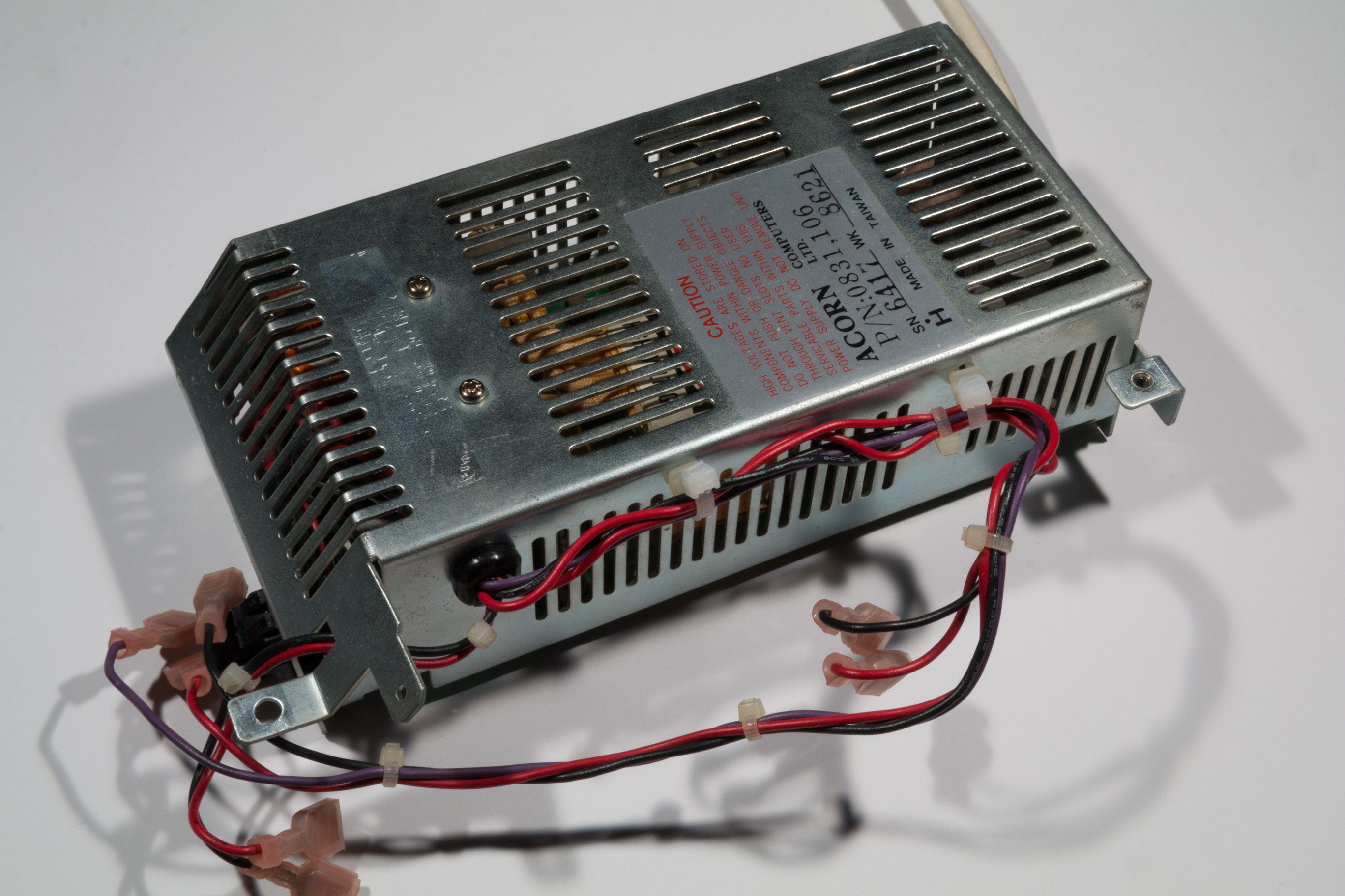
The Acorn BBC Master 128 computer (and variants such as the Turbo and 512) come with a 35W switched mode power supply unit. For general use the power supply is sufficient, however for applications where more peripherals are required or for machines where the power supply has failed, this project demonstrates how to fit a modern 60W switch mode power supply as a replacement for the original.
Please note that replacement of this supply involves wiring and components that will be handling mains electricity and should not be attempted unless you know what you are doing. If you are unsure, please find a qualified engineer and ask them to perform the modifications for you. Please note that the author does not guarantee accuracy and, as with any modification to the Acorn Master you run the risk of inadvertently breaking your computer. Please ensure that you use the correct ESD protection when performing any service work on the computer and take adequate safety measures when dealing with mains electricity.
Replacement power supply
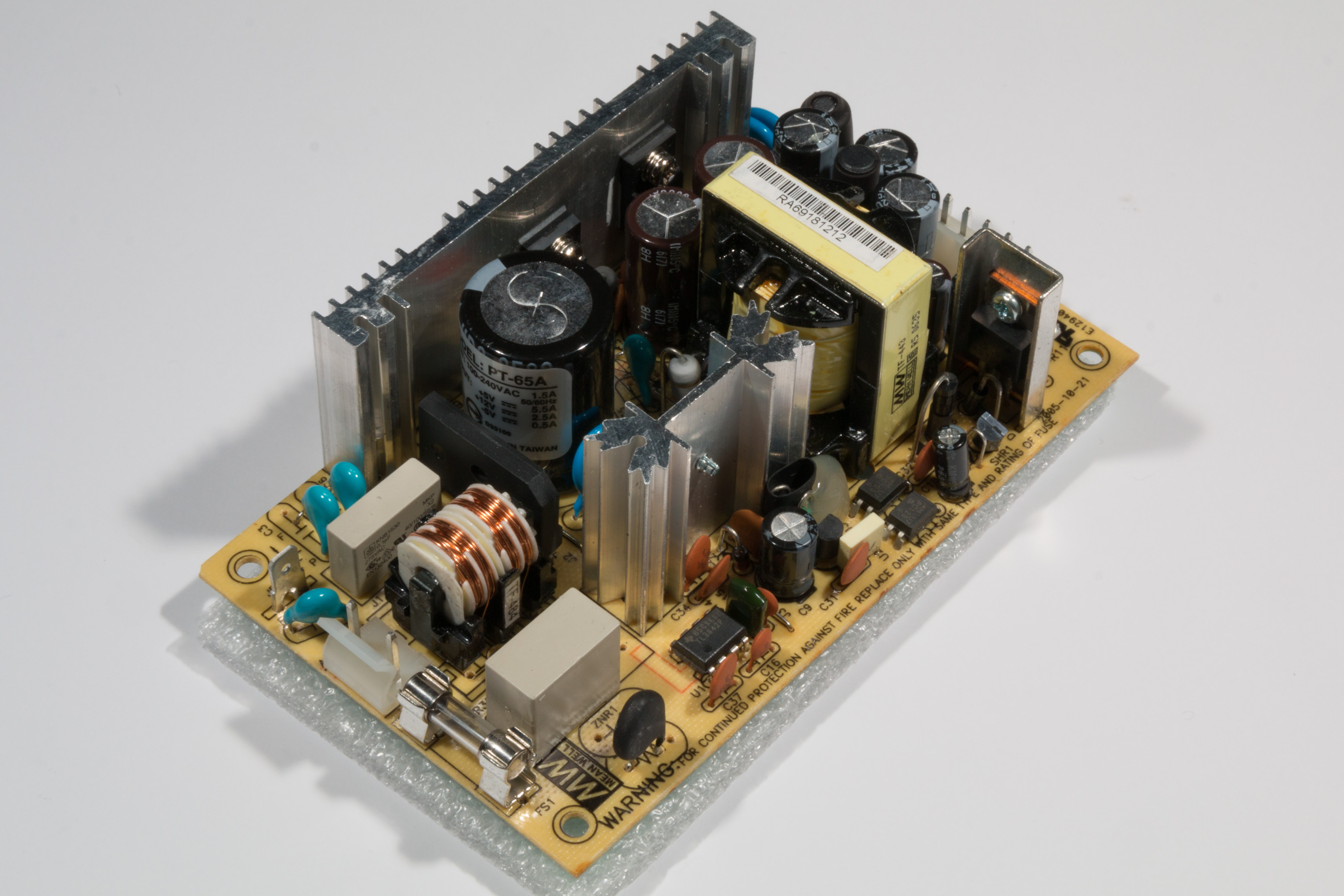
The replacement power supply is a Mean Well PT-65A 3 output switch mode power supply unit which is widely available from electronic component distributors. To assess the suitability of the power supply it is important to compare the output characteristics of the original supply to the PT-65A.
The BBC Master service manual does not contain details of the power supply however it is very similar to the supply found in the BBC Model B and B+ machines. The service manual for these machines gives the following power supply specifications:
- Total output power 35W
- 5V – 3.5A (quoted as 3.75A for the BBC B)
- -5V – 0.1A
- 12V – 1.25A
The power consumption of the computer itself can be estimated by subtracting the rated maximum current from the external power connector (located under the computer) which is labelled as follows:
- +5V 1.25A
- +12V 1.25A
- -5V 0.075A
This indicates that the computer uses approximately 2.25A @ 5V, 0.025A @ -5Vs and 0A @ 12V (since the 12V power is only used by the external connector).
The Mean Well PT-65A datasheet states the following specifications for the replacement power supply:
- Total output power 60W
- 5V – 5.5A (peak 7A)
- 12V – 2.5A (peak 3.2A)
- -5V – 0.5A (peak 0.7A)
It can be clearly seen (from the datasheet) that the new power supply out performs the original both in terms of output power and efficiency. The PT-65A also provides short-circuit protection, overload protection and over voltage protection.
Required parts
In order to connect the power supply and make the required wiring loom for the BBC Master you will need a number of parts, wire and tools.
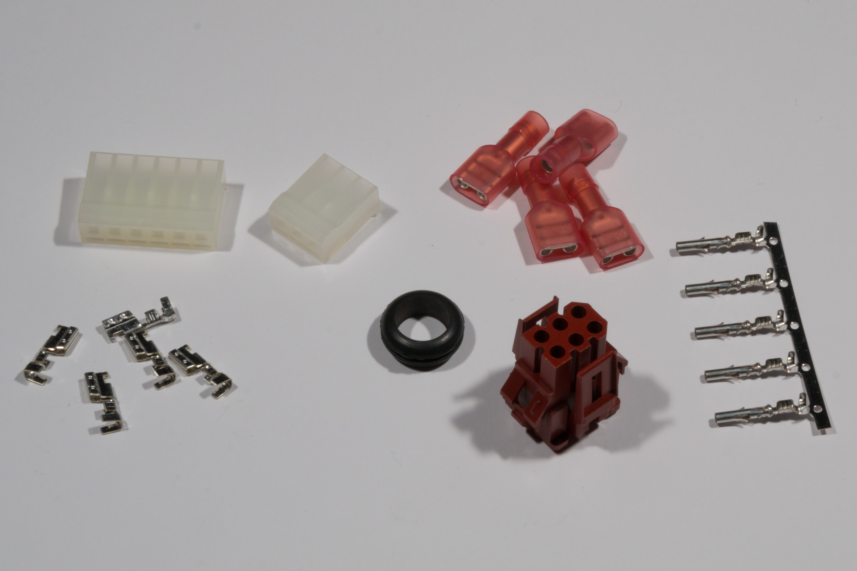
The following list shows the required parts for the power supply modification:
- 1x Mean Well PT-65A power supply – Distrelec article number 169-94-742
- 10x Blade receptacle 6.3×0.8mm (fully insulated) – Distrelec article number 148-20-754
- 1x Ring terminal (insulated) – Distrelec article number 148-20-876
- 1x 6 pole Molex crimp housing – Distrelec article number 143-01-271
- 1x 3 pole Molex crimp housing – Distrelec article number 143-01-268
- 8x Molex crimp contact – Distrelec article number 143-00-981
- 8cm of Single core PVC yellow 0.5mm2 (AWG20) stranded wire – Distrelec article number 300-09-476
- 117cm of Single core PVC red 0.5mm2 (AWG20) stranded wire – Distrelec article number 300-09-470
- 122cm of Single core PVC black 0.5mm2 (AWG20) stranded wire – Distrelec article number 300-09-462
- 57cm of Single core PVC violet 0.5mm2 (AWG20) stranded wire – Distrelec article number 300-09-474
- 1x TE Connectivity Miniature Rectangular II crimp connector housing – RS Components article number 709-9993
- 5x TE Connectivity Miniature Rectangular crimp terminal – RS Components article number 710-0545
- 4x M3x12mm screws and nuts
- 8x M3 Washers
- 1x 10mm inner diameter rubber cable grommet
- 3x 17cm of mains cable (blue, brown and green)
In addition you will need appropriate crimping tools for both the blade/ring terminals, the Molex crimp terminals and the TE connectivity terminals. You will also require access to a 3D printer or 3D printing service in order to create the required brackets (see below).
In order to fit the new supply into the original Acorn power supply case you will need to first remove the original power supply board from the case.
Assembling the wiring looms
Mains power connection
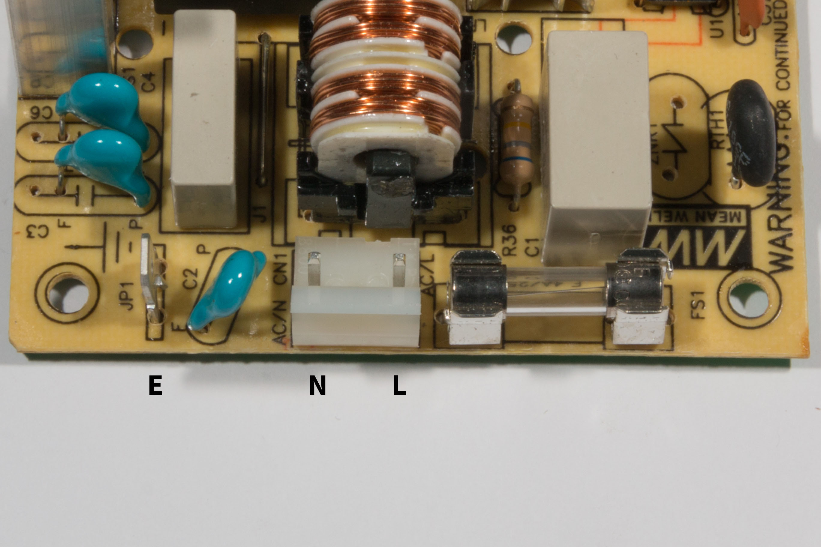
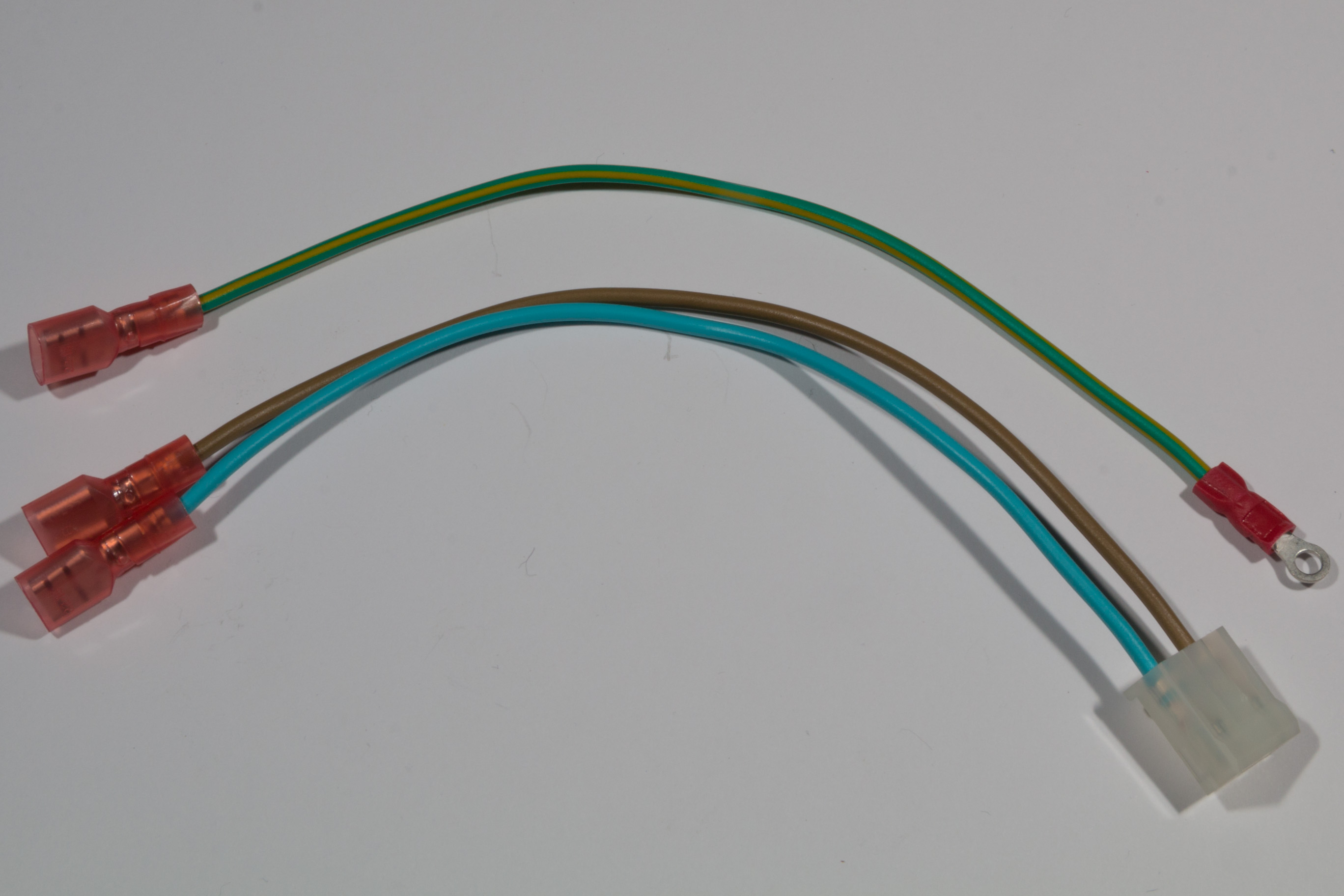
To connect the mains power to the PT-65A you will need 3 equal (17cm) lengths of mains cable. Strip one end of each cable and crimp a 6.3mm blade to each. For the earth cable (the green/green-yellow cable) you will need to crimp a ring terminal. On both the blue and brown cables crimp a molex crimp contact to each.
The pin-out of the mains and earth connector on the PT-65A is shown in the following picture, make sure you put the cables on the correct sides of the 3 pin molex connector:
Once complete the cables should look like the following picture:
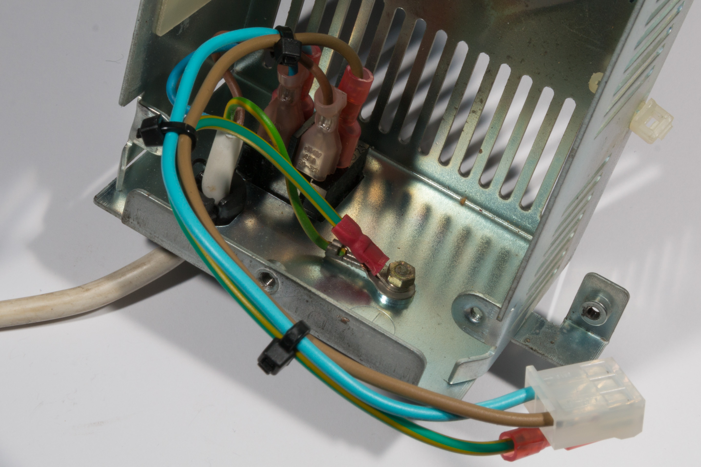
The mains cable is fitted to the metal case of the original Acorn power supply as shown in the following picture:
Computer power connection
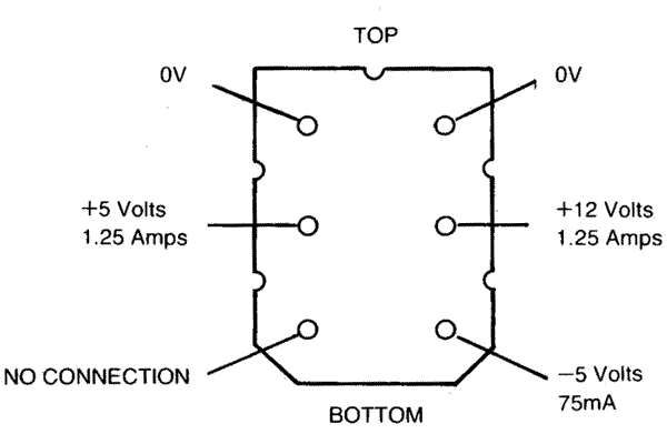
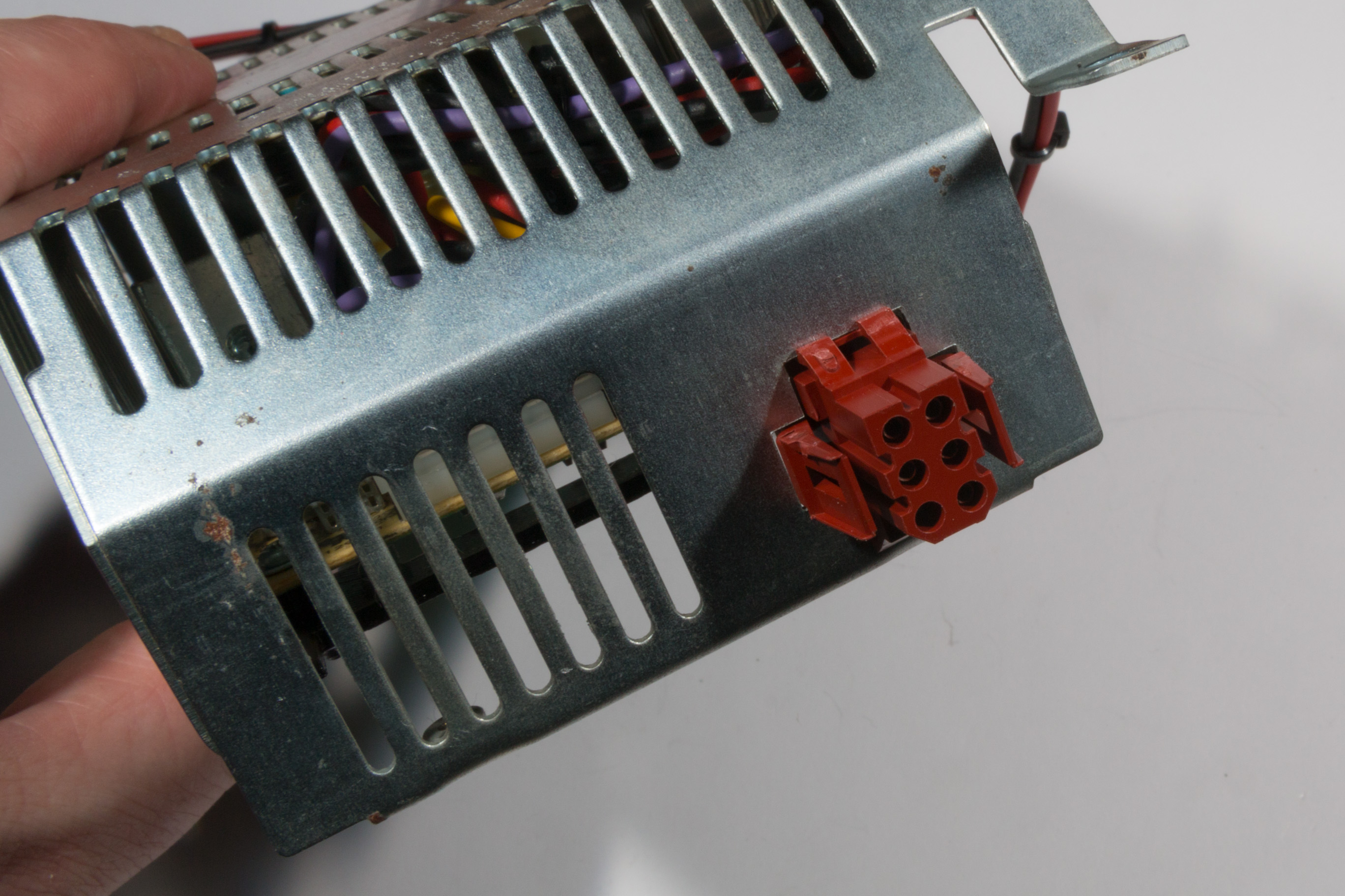
The PT-65A provides 3 different power output levels and ground for the computer. The pin-out of the PT-65A is as shown in the following picture:
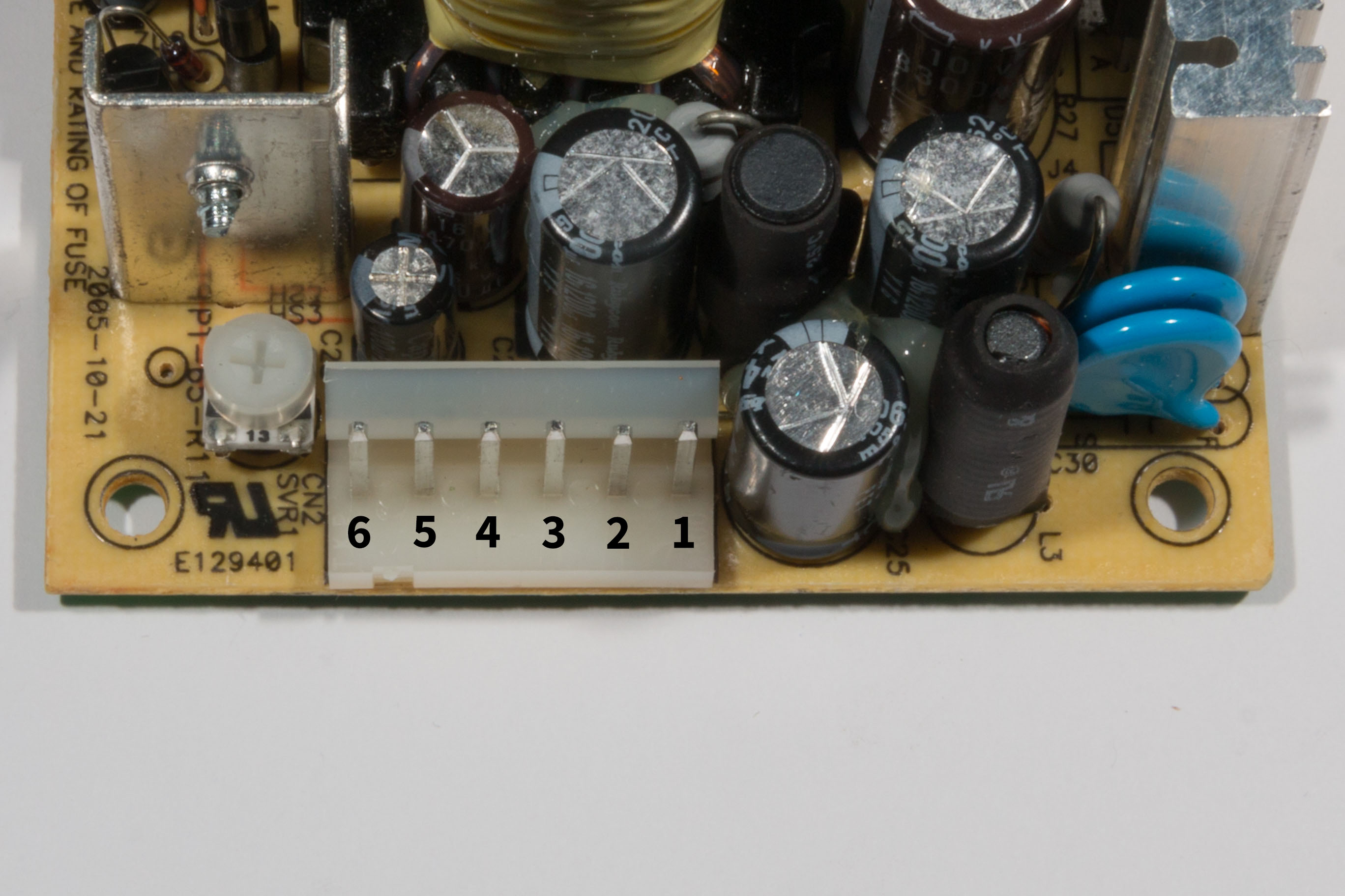
The pin assignments (from the datasheet) are as follows:
- Pin 1 – 12V
- Pin 2 – 5V
- Pin 3 – 5V
- Pin 4 – Ground
- Pin 5 – Ground
- Pin 6 – -5V
In order to connect to the power supply you will need to cut the following cables and crimp them into the connector for each pin (most pins require two cables connected to the same pin):
- Pin 1
- 1x 8cm yellow cable
- Pin 2
- 1x 8cm red cable
- 1x 22cm red cable
- Pin 3
- 1x 38cm red cable
- 1x 49cm red cable
- Pin 4
- 1x 8cm black cable
- 1x 22cm black cable
- Pin 5
- 1x 38cm black cable
- 1x 49cm black cable
- Pin 6
- 1x 8cm violet cable
- 1x 49cm violet cable
You will also need to cut an additional 5cm black cable for the external power connector.
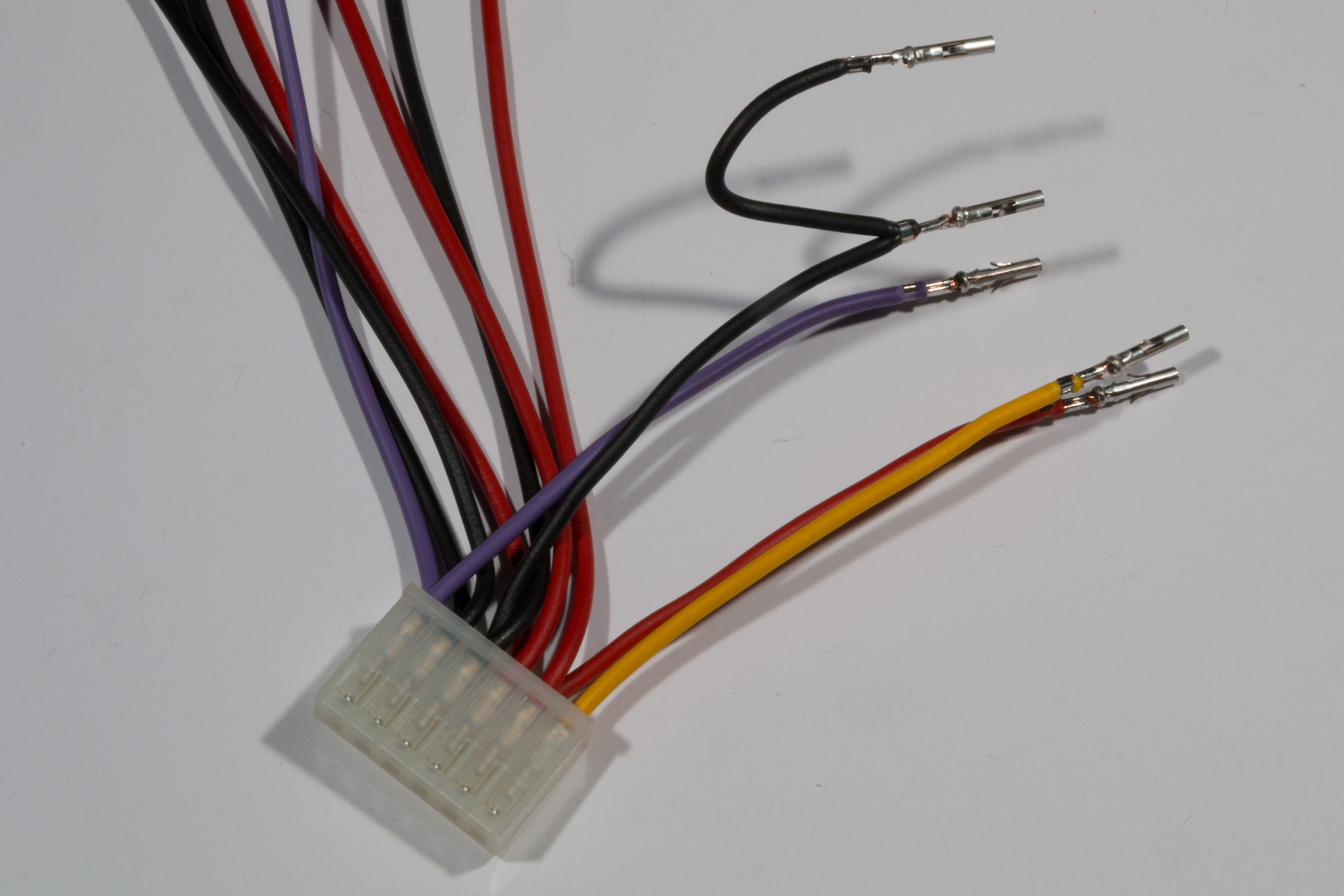
The cable should now look like the following picture:

Seperate out the 8cm cables (these are all for the external power connector) and crimp the TE connectivity connectors to the wires. For the black cable from pin 4 of the Molex connector you will need to crimp the cable along with the extra 5cm black cable and then crimp a connector to the other end of the 5cm cable as shown in the following picture:
The crimped connectors should then be inserted into the TE Connectivity Miniature Rectangular II crimp connector housing according to the following diagram:
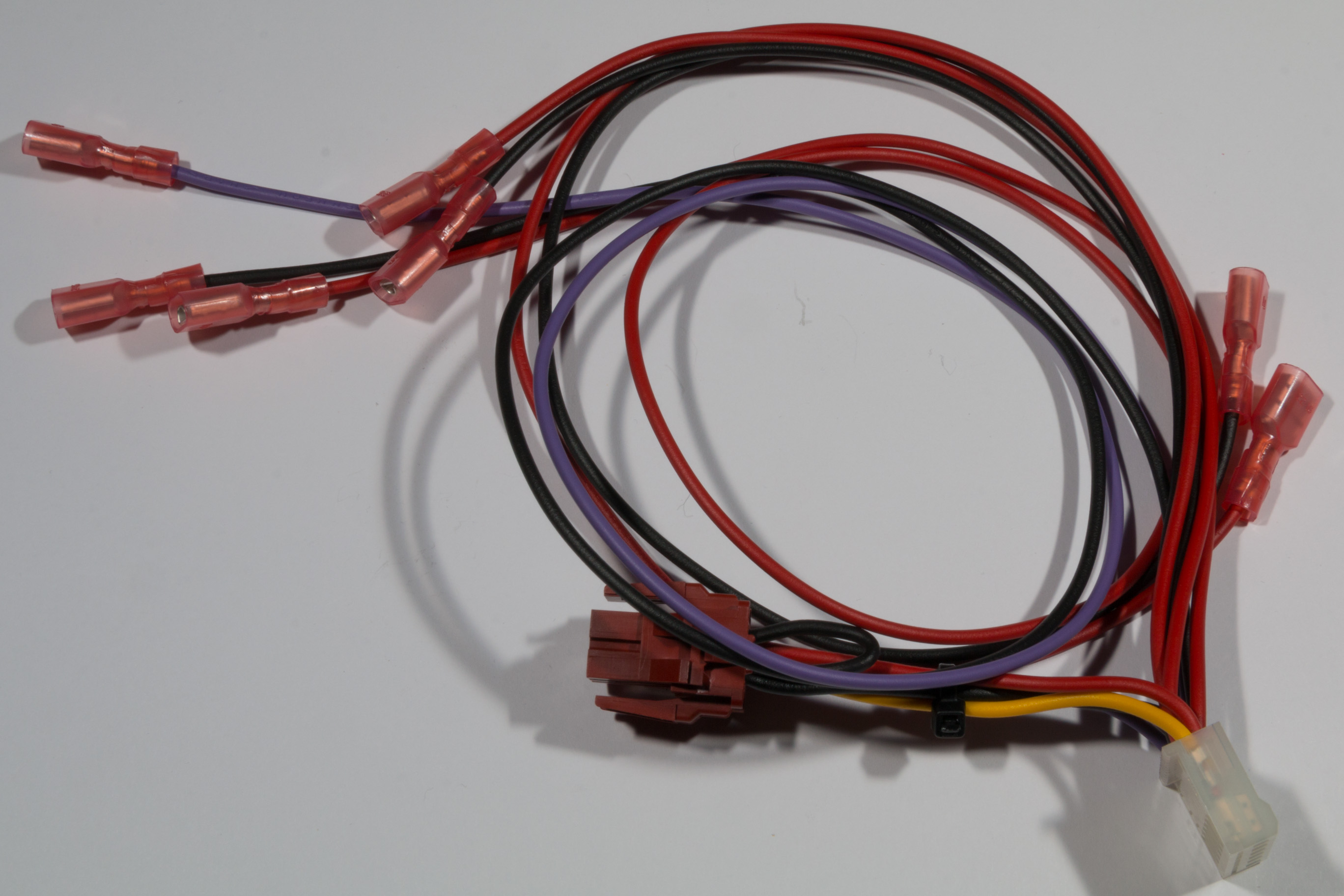
Next strip all of the unconnected wire ends and crimp 6.3mm blade recepticals to all of the cables. The finished cable should look like the following picture:
Mounting the power supply in the metal case
Since the PT-65A is a smaller board than the original Acorn power supply it is necessary to use 2 brackets that adapt the original case to the new foot-print. These brackets can be simply 3D printed from the STL file supplied below. Each bracket takes about 30 minutes of printing time and can be printed using PLA with 20-25% in-fill.
PT65A bracket for Acorn BBC Master
Note that the latest version of the bracket (which will probably be better to use than the link above) is available from the project GitHub. The GitHub repository also includes the original OpenSCAD source files allowing you to customise the bracket if required:
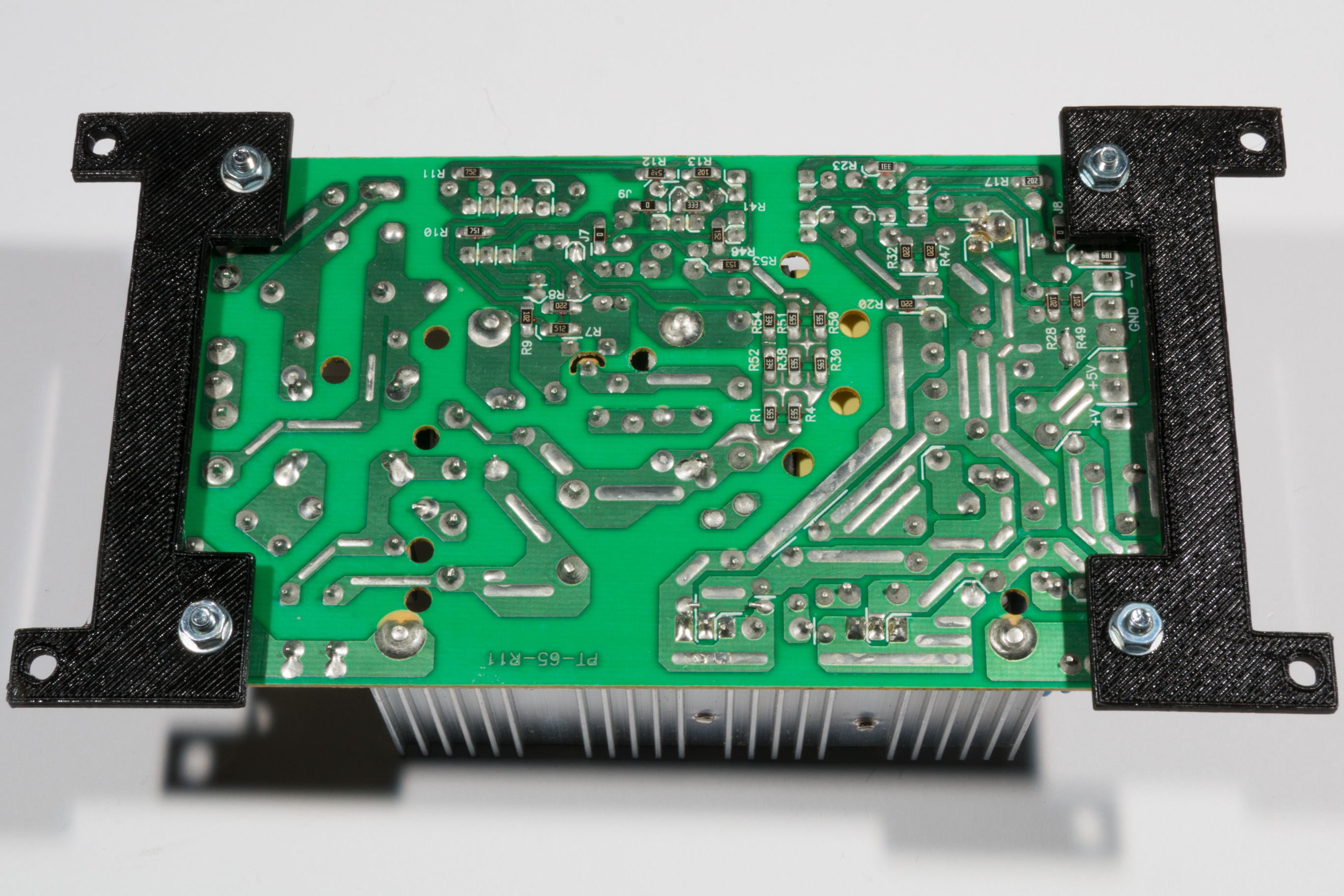
Attach the two printed brackets to the PT-65A using the M3 screws, washers and nuts. Use a washer on either side of the screw to avoid damaging the plastic when the nuts are tightened. The brackets should be mounted as shown in the following picture:
Once the brackets are fixed, flip over the power supply board and attach both the mains and computer power cables made in the previous steps (don’t forget to connect the earth cable to the connector on the power supply. It must be earthed for correct and safe operation!). The mains cables should be long enough that you can do this with the power supply next to the power supply case as shown in the following picture:
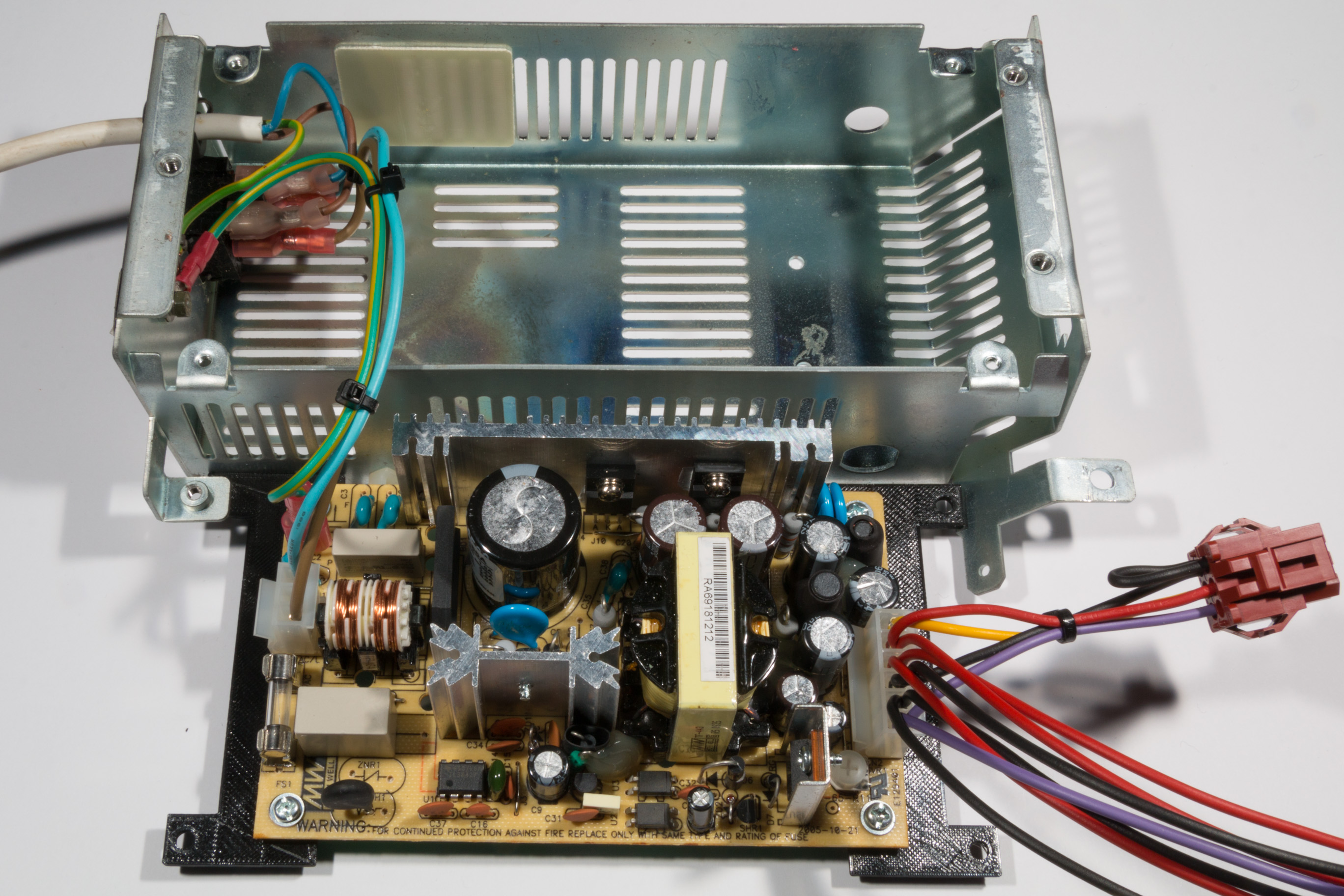
Next you will need to thread the long cables through the hole in the side of the power supply case, then flip the power supply board on to the top of the case and push the external power connector into the case (note: Make sure you get the power connector the right way up, the curved part of the connector should be at the bottom of the case. Pushing the connector though can be quite tough, but it does fit). Once the long cables are fitted, slide the rubber grommet over the cables and fit into the side of the metal case to prevent the wires from rubbing on the edge of the metal.
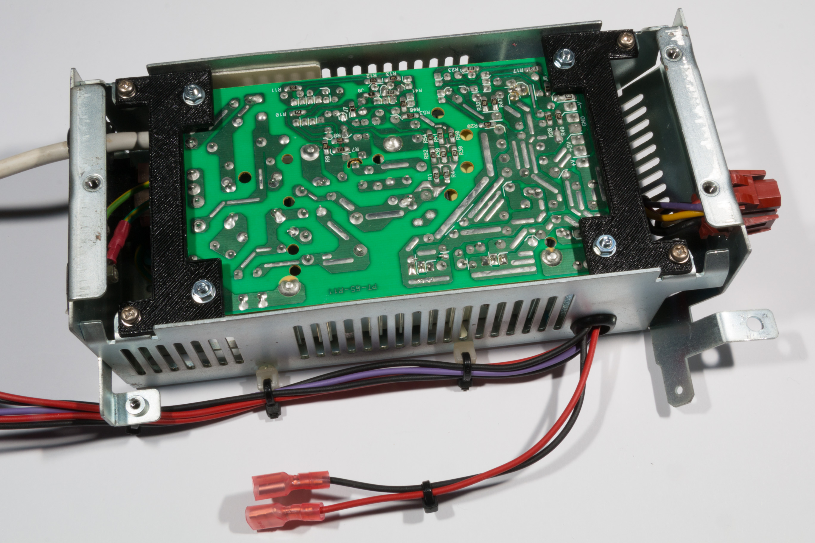
Once the external power connector is in place you can place the power supply down into the case and align the screw holes with the bracket. Be careful to fold the excess wires out of the way so they don’t prevent the power supply board from fitting correctly. Once aligned simply screw the board in place using the original 4 screws from the case. You will need to liberally apply zip-ties to the various cable lengths to make sure it is neat and the cable runs don’t easily tangle. The finished power supply unit should look like the following picture:
Mounting the power supply in the Master
To mount the power supply back into the Master simply place it back in its original location and wire it up as per the original supply. Make sure the ground, 5V and -5V connectors are in the correct place.
Once connected it is a good idea to check the power output of the new supply by measuring the 5V power output (this must be done while the power supply is under load). If the power output is not 5Vs you can simply adjust the output level using the potentiometer on the power supply board. This can be accessed (at an angle) through the left screw hole on the top of the power supply case (which originally screwed into the heat sink of the old supply). The finished supply should look like the following picture:
