Acorn Econet Clock V2
Contents
Continuing on from my first Acorn Econet Clock project, I received some good feedback and advice from other Acorn enthusiasts and decided to make a slightly more complex version 2 of the clock. The original design was simplistic enough to be built on stripboard however, this revised design is built on a custom PCB with a large ground plane to keep signal noise to a minimum.
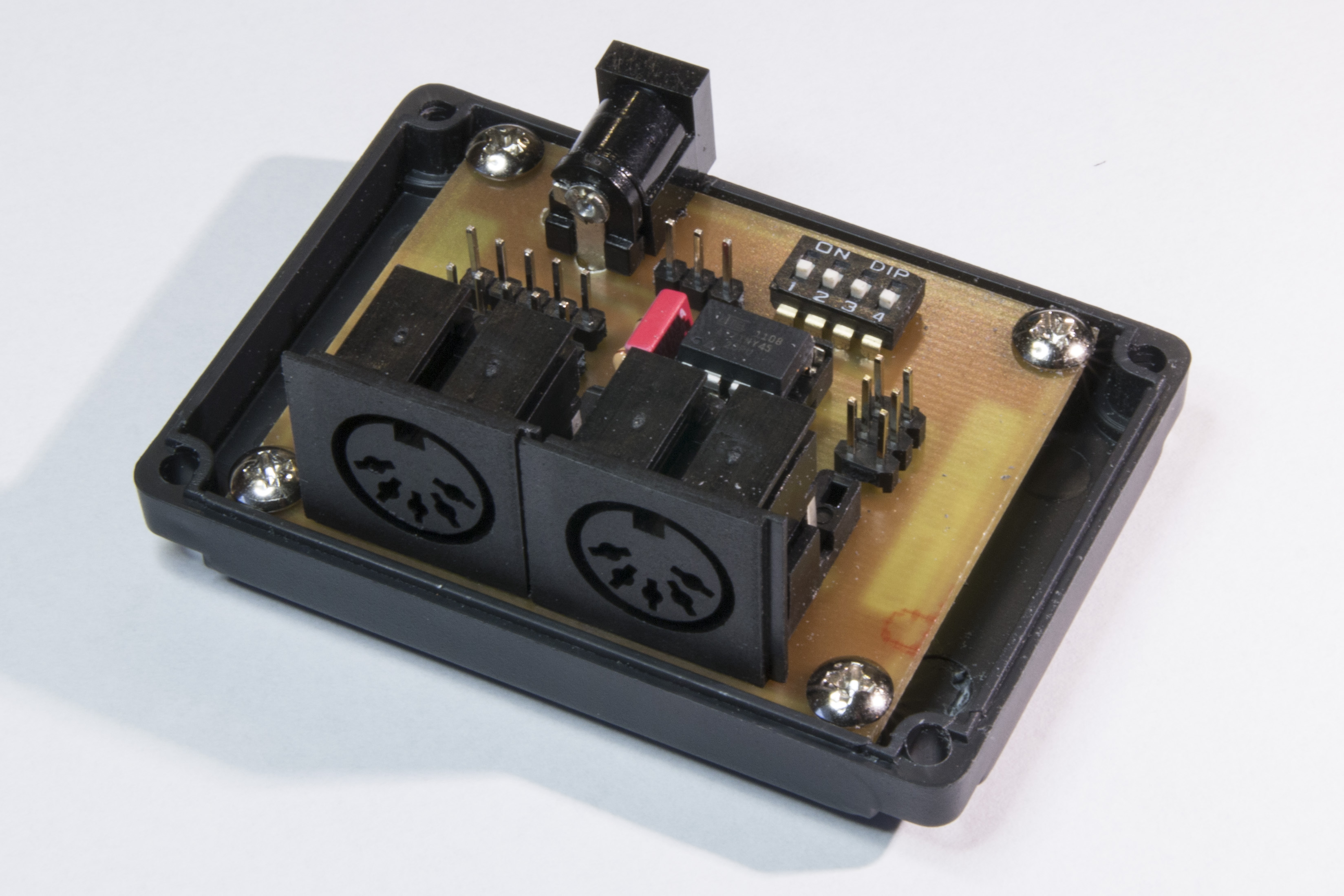
Econet Clock V2 (internal view)
This design, like the original, is very economical in terms of components, the only IC used is an ATtiny45. As additions to the original project, this design includes two on-board Econet DIN connectors and an on-board power supply jack. The design includes headers for both Econet (2 DIN sockets) and power so you can choose if you wish to mount the connectors on the PCB or externally. In addition you can also choose to connect both the on-board and external DIN sockets allowing 4 sockets to be connected. This is useful if you want a compact clock and hub for up to 4 machines with minimal cabling.
The primary additional feature is the DIP switch which allows you to choose from 8 preset clock configurations. Although the original project allowed you to set the clock configuration in firmware, this project adds a DIP switch for users that do not have access to an AVR programmer (for example, when the clock was supplied to you by someone else). Of course, by altering the firmware, you can choose your own presets and the code comments explain how to do this.
Hardware
Schematic
The schematic for Acorn Econet clock v2 is based on the Atmel ATtiny microcontroller which is a small 8 pin device available in DIP format. Although the microcontroller is clocked from its internal 8MHz oscillator, the PLL and PWM features of the processor are used to clock an internal timer to 64MHz that is more than adequate for producing the 200-400 KHz asymmetric differential clock signal required by Econet.
Previously the Econet clock designs included a differential line driver (such as the defunct SN75159N in the BBC Micro and the AM26LS30 found in later Econet modules). The differential line driver takes a non-inverted clock signal from the clock generator and splits it into the positive (non-inverted) and negative (inverted) signals required for a two-wire differential output. This design takes advantage of the ATtiny45’s PWM output feature that can supply a differential output directly from the OC1B and !OC1B (NOT OC1B) outputs removing the need for an external IC.
Note that the power input to the circuit ”’must”’ be a regulated 5V supply; as the circuit does not contain a regulator. Since the power supply sets the voltage on the clock signals it is very important to ensure the supply does not exceed the TTL levels required by Econet.
The design does not need a differential line driver since the AVR can generate both the positive and negative clock signals using it’s on-board PWM module. This has the advantage of both simplifying the circuit as well as improving the signal (since a line driver is essentially an opamp it does not drive the output signal rail-to-rail (i.e. from 0V to 5V) – however the AVR’s PWM can. This drives the line with more mW of signal than possible with a line driver which should improve the clock’s performance in longer/larger networks).
The schematic for the clock design is shown below:
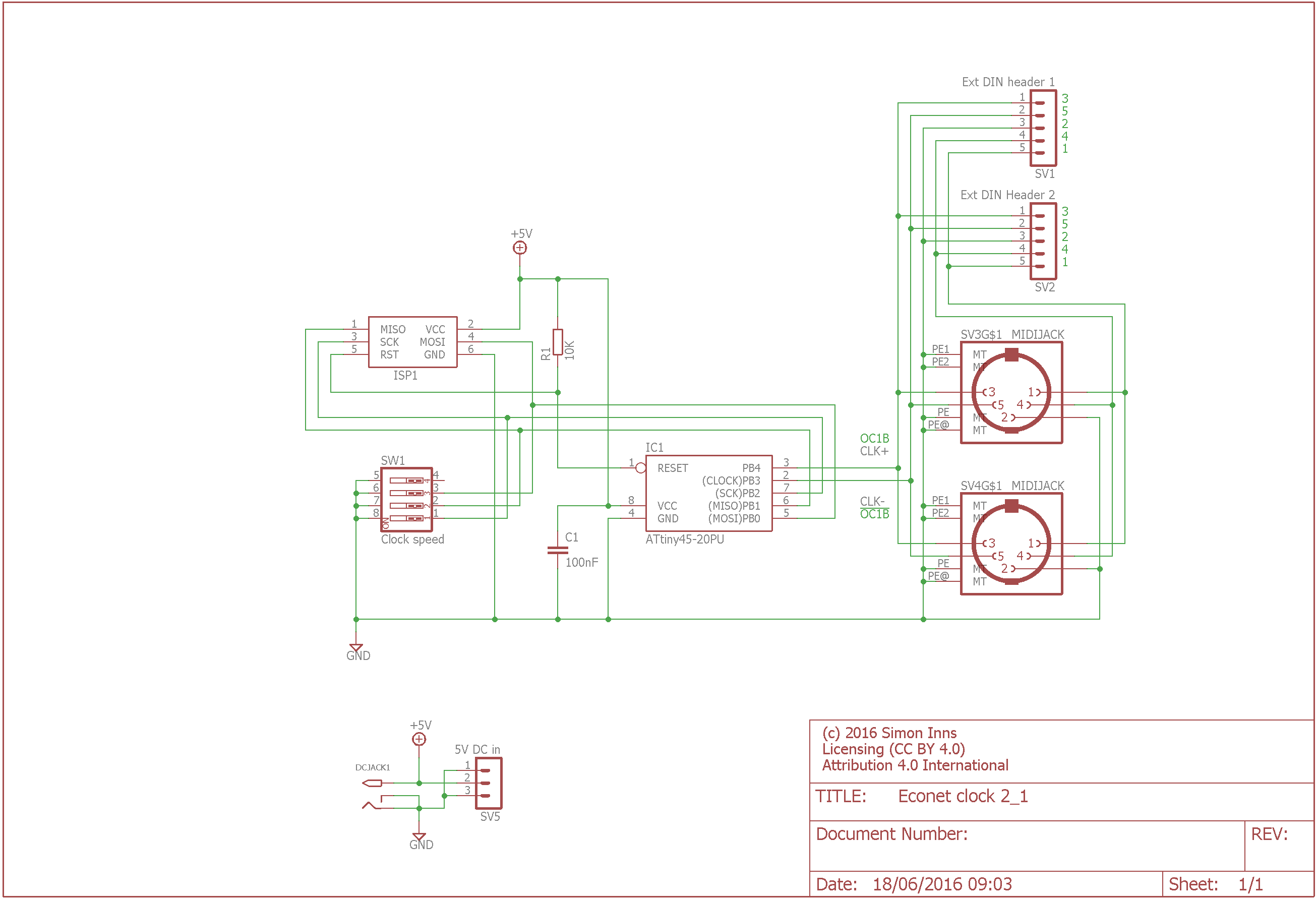
Econet Clock V2 Schematic
PCB Design
The clock is built on a single-sided PCB with a large ground plane area to reduce signal noise. The PCB design is suitable for making using the UV transfer technique:
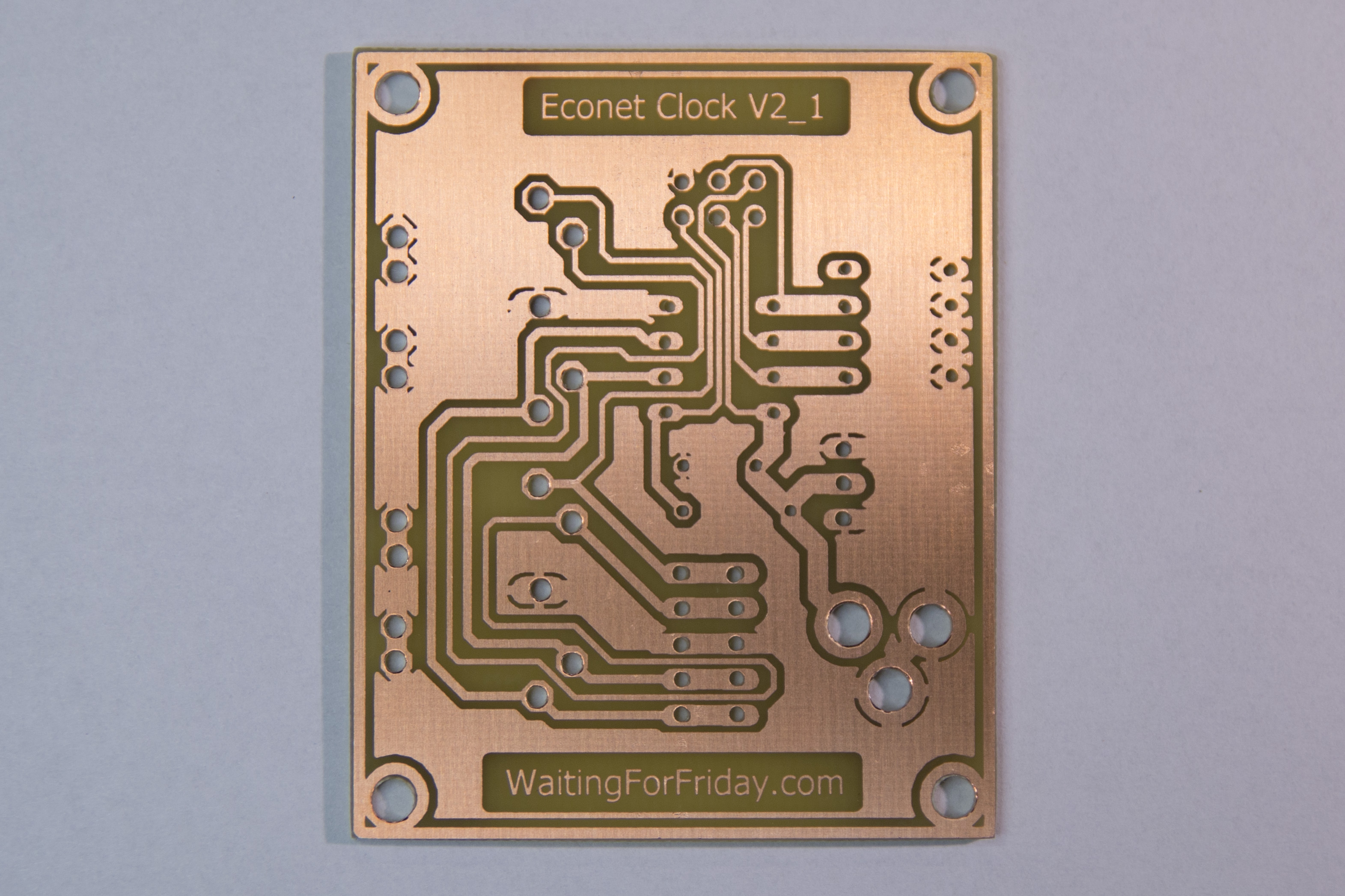
Econet clock V2 PCB
If you wish to use external DIN connector and/or power connectors the pin out and cable construction is the same as documented in Acorn Econet Clock. The on-board DIN footprint is suitable for 2 styles of DIN socket (with either wide or narrow earth pins). The wide-pinned version is the same as used in the BBC micro itself. These sockets are also common in MIDI devices so they are widely available.
Firmware
The firmware project can be downloaded from the bottom of this article and contains a GPL licensed firmware project which can be opened in Atmel Studio 7. The firmware configures the ATtiny Timer/Counter1 to produce the require differential clock signal depending on the position of the DIP switches. The overall frequency of the clock and the length of the mark (the positive pulse) for the presets can be freely altered in the source code; the source code is heavily commented and contains all the instructions required to make simple modifications to the clock settings. As the ATtiny is clocked by its internal 8MHz oscillator there is some noticeable jitter and inaccuracy in the clock output, but perfectly within tolerance of the required Econet clock signal (and has been tested using both a BBC micro and an Archimedes A440/1). There are 8 preset clock configurations available in the firmware:
DIP SW – Period (uS) – Mark (uS)
- 0000 – 5.00 – 1.000
- 0010 – 4.00 – 0.750
- 0100 – 4.00 – 0.500
- 0110 – 3.00 – 0.500
- 1000 – 3.00 – 0.250
- 1010 – 2.00 – 0.500
- 1100 – 2.00 – 0.250
- 1110 – 2.00 – 0.125
Note that the 4th DIP switch (the right-most) is not used, only the first 3 switches have any affect on the generated clock. The left most switch is the most significant bit of the configuration number and the right-most is the least.
The following image shows the output from all 8 configurations (captured on a DSO) along with the actual measurements (note that, since the AVR is internally clocked, there will be some variance between chips):
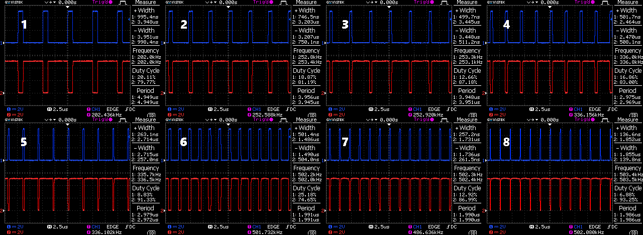
Econet clock V2 output traces for all 8 configurations
The top channel (channel 1) shows the non-inverted clock output and the bottom channel (channel 2) shows the inverted output.
The PCB also includes a 6 pin AVR programming header to allow the ATtiny to be programmed without removing it from the PCB. When programming the ATtiny all DIP switches should be set to ‘off’ to prevent the circuit from interfering with the SPI programming.
Case
The PCB is designed to fit into a G027N case from Kemo Electronics. The case is 72 x 50 x 35mm. The top part of the case will need to be cut to allow access to the DIN sockets and the 5V power jack. Mounting the clock in a case is, of course, optional, but helps to protect the clock circuitry from dirt and metal objects that could case a short-circuit. The completed clock mounted in it’s case is shown in the following picture:
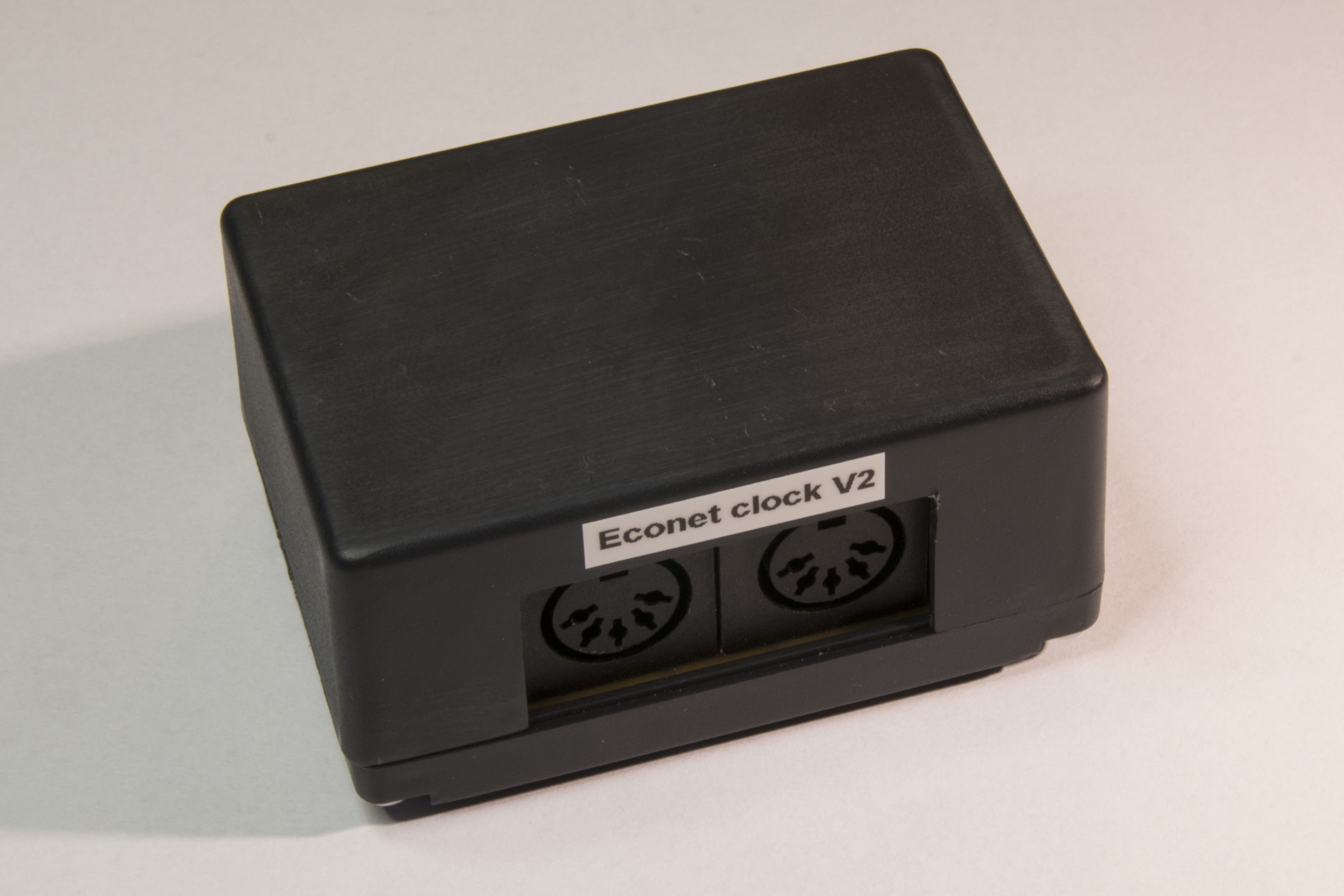
Econet clock V2 mounted in a plastic case
Conclusions
I hope you find this design both useful and flexible.
As the design is open-source and open-hardware I positively encourage you to embrace, modify and even build and sell the design. My intention is to help as many Acorn enthusiasts as possible!
Files for download
The source code, project files and Eagle CAD schematics and board files are available on GitHub: